A speed limit control method for distributed electric drive vehicles

A vehicle speed limit control, electric drive technology, applied in electric vehicles, control drives, vehicle components, etc., can solve the control requirements that cannot take into account torque output and speed limit, acceleration, torque discontinuity and other problems, to achieve The effect of improving reliability and fault-tolerant operation

Active Publication Date: 2020-09-04
江苏迈吉易威电动科技有限公司
View PDF11 Cites 0 Cited by
  • Summary
  • Abstract
  • Description
  • Claims
  • Application Information

AI Technical Summary

Problems solved by technology

[0004] At present, there are generally three methods for the speed limit of centralized-driven new energy vehicles. One is to clear the given torque command when the motor exceeds the maximum speed, and when the motor speed is lower than the set speed, then re-pass the accelerator pedal. Given a torque command, if the driver keeps stepping on the accelerator pedal deeply, the motor speed will fluctuate between the set speed and the maximum speed, resulting in unstable vehicle speed, and frequent acceleration and deceleration will seriously affect driving Another method is that when the motor reaches the highest speed, the motor controller enters the speed mode to make the motor run at the highest speed, and when the given torque of the accelerator pedal is less than the torque command output by the speed loop of the motor controller, Then exit the speed mode and directly give the torque command by the accelerator pedal. This method will cause the motor controller to switch directly between the speed mode and the torque mode, so there is a problem of discontinuous torque during the switching process
The third method is to linearly reduce the input torque when the speed is higher than the set speed. This method cannot take into account the control requirements of torque output and speed limit of each drive motor in a multi-motor system in a distributed drive vehicle.

Method used


Image

  • A speed limit control method for distributed electric drive vehicles
  • A speed limit control method for distributed electric drive vehicles
  • A speed limit control method for distributed electric drive vehicles

Examples


Embodiment Construction

[0036] The present invention will be further explained below in conjunction with the accompanying drawings.

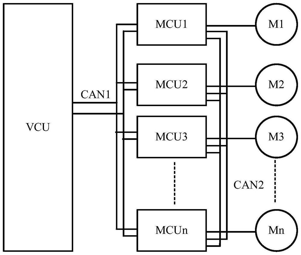
[0037] A distributed electric drive vehicle speed limit control method, based on such as figure 1 The control device shown includes a power battery, a vehicle controller VCU, drive motors M1, M2, Mn, motor controllers MCU1, MCU2, MCUn, a first communication bus CAN1 and a second communication bus CAN2, each motor controller externally With 2 CAN buses. The power battery is connected to the motor controller through the positive and negative command buses, the three-phase output of the motor controller is connected to the three-phase input of the driving motor, and the position sensor and temperature sensor of the motor are connected to the low-voltage signal interface of the motor controller. One of the buses of each motor controller MCU1, MCU2, and MCUn is connected to the CAN bus of the vehicle controller VCU after being jointed, and communicates with the vehicle con...


PUM


Abstract

The invention discloses a distribution type electrically driving vehicle speed limit control method. Accelerator pedal information is firstly collected, torque T0 given by a accelerator pedal is calculated, then the current rotating speed value Ni, allowable maximum torque Tmaxi, allowable maximum working rotating speed Nmaxi and disoperation condition information Si of all driving motors are collected, motor rotating speed Nmax corresponding to the highest vehicle speed allowable highest vehicle speed of an existing vehicle and the average rotating speed Navg of a non-fault motor are calculated, the amount of the motor rotating speed Nmax and the amount of the average rotating speed Navg are prepared, the smaller one is the speed limiting value Nlimit of all driving motors, and the torqueorder of all driving motors are calculated according to a speed limiting and controlling unit. According to the distribution type electrically driving vehicle speed limit control method, the difficult problem that control of all driving motors and a whole vehicle speed of a distribution type electrically driving vehicle is complex is efficiently solved, and requirements of vehicle high speed limiting and controlling of part of the motors are reconciled.

Description

technical field [0001] The invention relates to a method for speed limit control of a distributed electric drive vehicle. Background technique [0002] The main structural feature of distributed drive electric vehicles is that the drive motor is directly installed in or near the drive wheel, which has the outstanding advantages of short drive transmission chain, efficient transmission, compact structure, and high utilization of interior space. Compared with traditional internal combustion engine vehicles Ratio, the driving motors of each wheel can be independently controlled, and the torque of each wheel can be distributed according to any ratio within its capability range, even driving one side and braking the other, enhancing the direct yaw moment control capability; reducing the braking lateral The deceleration effect on the vehicle in the pendulum moment control increases the speed of the cornering vehicle. In addition, the independent control of the driving force and b...

Claims


Application Information

Patent Timeline
Patent Type & Authority Patents(China)
IPC IPC(8): B60L15/20
CPCY02T10/72
Inventor 不公告发明人
Owner 江苏迈吉易威电动科技有限公司
Why Eureka
Try Eureka