
Vertical take-off and landing fixed wing

A fixed-wing, vertical take-off and landing technology, applied in the field of aircraft, can solve the problems of UAV load capacity reduction, aerodynamic influence, etc., and achieve the effect of small wetted area and increased overall resistance

Active Publication Date: 2017-02-15
丰翼科技(深圳)有限公司
View PDF7 Cites 3 Cited by
  • Summary
  • Abstract
  • Description
  • Claims
  • Application Information

AI Technical Summary

Problems solved by technology

[0003] In view of the above-mentioned defects or deficiencies in the prior art, it is desired to provide a vertical take-off and landing fixed wing to solve the problems in the prior art that cause the load capacity of the UAV to decrease and bring negative aerodynamic effects. question

Method used


Image

  • Vertical take-off and landing fixed wing
  • Vertical take-off and landing fixed wing

Examples


Embodiment Construction

[0009] The application will be further described in detail below in conjunction with the accompanying drawings and embodiments. It should be understood that the specific embodiments described here are only used to explain related inventions, rather than to limit the invention. It should also be noted that, for the convenience of description, only the parts related to the invention are shown in the drawings.

[0010] It should be noted that, in the case of no conflict, the embodiments in the present application and the features in the embodiments can be combined with each other. The present application will be described in detail below with reference to the accompanying drawings and embodiments.

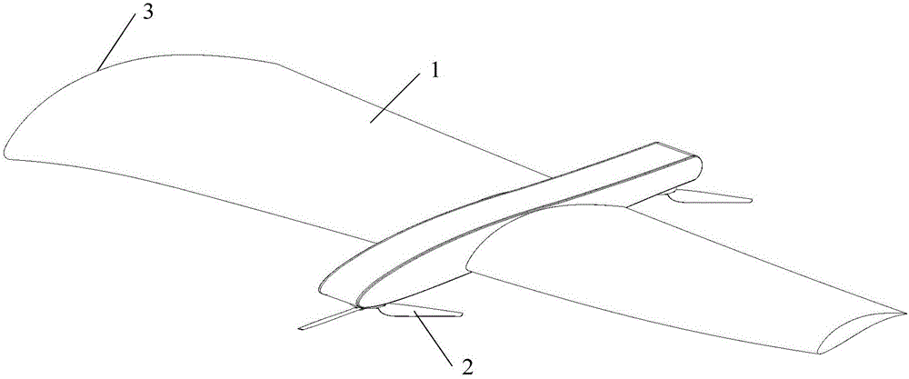
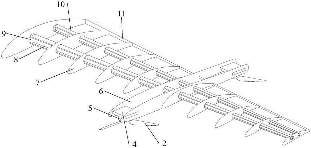
[0011] see figure 1 , figure 2 The vertical take-off and landing fixed wing provided by the embodiment of the present invention includes an inner skeleton and a skin 1 covered outside the inner skeleton, the inner skeleton includes a spar, and a plurality of first ribs 7 are conne...


PUM


Abstract

The invention discloses a vehicle take-off and landing fixed wing. The vehicle take-off and landing fixed wing comprises an inner framework and skin arranged outside the inner framework in a wrapping mode. The inner framework comprises a wing beam, wherein a plurality of first wing ribs are connected to the wing beam, a second wing rib is also connected to the wing beam and located on the middle section of the vehicle take-off and landing fixed wing, the relative thickness of the second wing rib is smaller than that of each first wing rib, the length of the second wing rib is greater than that of each first wing rib, and motor bases are connected to the ends of the second wing rib. According to the scheme, the first wing ribs are arranged on the swing beam, the second wing rib with the relative thickness being smaller than the relative thickness of each first wing rib is also arranged on the wing beam and serves as a mounting structure of a rotor, and the first wing ribs and the second wing rib are wing ribs of the wing, namely, mounting parts for rotor motors are provided on the premise that no extra structure is introduced, a too large wetted area is avoided, and particular destroy to the aerodynamic characteristic of the wing is avoided. Since no extra mechanism is introduced, negative influences on the load capacity of an airplane are avoided.

Description

technical field [0001] The present application generally relates to the technical field of aircraft, and in particular relates to a vertical take-off and landing fixed wing. Background technique [0002] With the hot commercial market of multi-rotor drones in recent years, drones have attracted more and more attention as a hot spot in the technology industry. However, quad-rotor drones have the disadvantages of short battery life and weak wind resistance. However, compared with traditional fixed-wing aircraft, it has the great advantage of lower take-off and landing requirements. Therefore, the development of fixed-wing UAVs that can take off and land vertically has become a hot topic in the field of research and engineering recently, and finding a way to perfectly integrate quadrotors and fixed-wing aircraft is an important part of this topic. At present, the most common method is to hang a cylindrical rod under the wing to connect the quadrotor motor and the fixed-wing wi...

Claims


Application Information

Patent Timeline
IPC IPC(8): B64C3/18B64C3/32
Inventor 张彬华
Owner 丰翼科技(深圳)有限公司
Learn More