
Low-resistance fairing of corrugate sheath

A technology of fairing and corrugated sleeve is applied in the field of low-resistance fairing of corrugated sleeve to achieve the effects of suppressing airflow separation, strong operability and simple structure

Active Publication Date: 2014-12-10
XIAN AIRCRAFT DESIGN INST OF AVIATION IND OF CHINA
View PDF4 Cites 0 Cited by
  • Summary
  • Abstract
  • Description
  • Claims
  • Application Information

AI Technical Summary

Problems solved by technology

According to the aerodynamic characteristics of the fairing, a good fairing hopes that the slenderness ratio can be adjusted according to the flight speed of the aircraft to avoid the appearance of the tail vortex area, but the fairing of the existing aircraft does not have this feature

Method used


Image

  • Low-resistance fairing of corrugate sheath
  • Low-resistance fairing of corrugate sheath
  • Low-resistance fairing of corrugate sheath

Examples


Embodiment Construction

[0015] The present invention will be described in detail below in conjunction with the accompanying drawings.

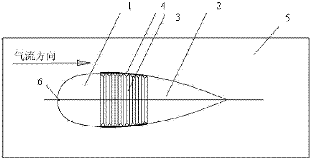
[0016] Described fairing is made up of fairing head 1, fairing rear part 2, fairing corrugated cover 3, surface elastic rubber 4, body surface 5, through hole 6. The fairing head 1 is fixedly riveted or bonded on the aircraft body surface 5, and a through hole 6 is left near the front end of the fairing head 1, that is, the stagnation point of the airflow, and the through hole communicates with the fairing inner cavity. The front end of the fairing bellows 3 is bonded to the rear end surface of the fairing head 1, the rear end of the fairing bellows [3] is connected with the fairing rear 2, and the fairing bellows 3 has good flexibility in the longitudinal direction , with good support stiffness in other directions. The surface elastic rubber 4 is bonded on the outside of the corrugated sleeve, and the bonding position is the peak position of the corrugated sleeve. ...


PUM


Abstract

The invention belongs to the technical field of airplane design, and relates to a low-resistance fairing of a corrugate sheath, which is improved on a plane fairing part. The fairing consists of a fairing head part, a fairing back part, a fairing corrugate sheath, a resilient surface rubber, a plane body surface and a through hole, wherein the fairing head part is fixedly riveted or bonded on the plane body surface, the through hole is arranged at the most front end of the fairing head part, i.e. near an airflow stationary point, the through hole is communicated with an inner cavity of the fairing, the fairing corrugate sheath is arranged in the position with the biggest cross section area of the fairing, the fairing corrugate sheath is bonded between the fairing head part and the fairing back part, and the resilient surface rubber is bonded on the outer surface of a wave crest position of the corrugate sheath. The low-resistance fairing of the corrugate sheath disclosed by the invention can be balanced between pressure drag and frictional drag, the shape of the fairing is self-adaptively changed according to flight speed, flow separation on the fairing under a high-speed condition is restrained, and the vortex intensity at the tail part of the fairing is improved, so that the differential pressure between the front and the back of the fairing is reduced and the plane flight resistance is reduced.

Description

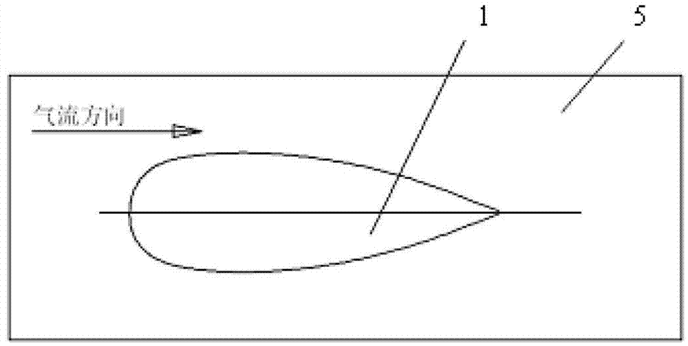
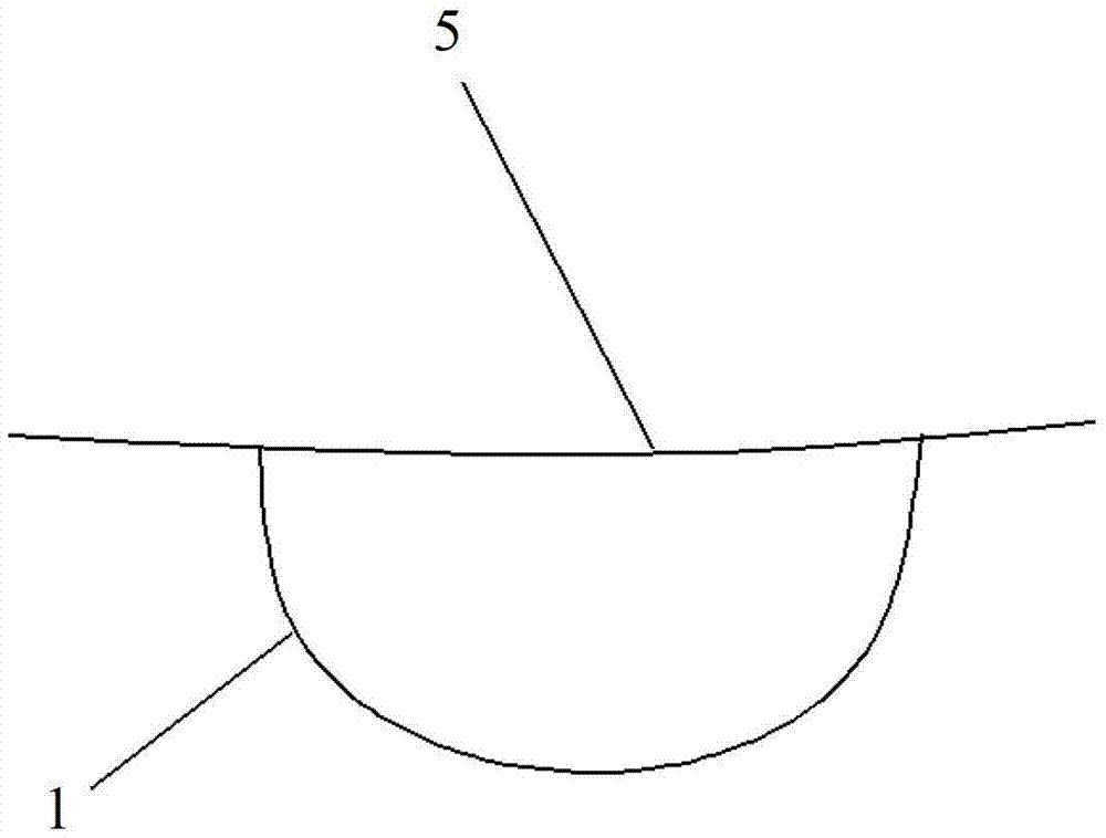
Technical field: [0001] The invention belongs to the technical field of aircraft design, and relates to a corrugated sleeve low-resistance fairing improved on aircraft fairing parts. Background technique [0002] Widely adopted by existing subsonic aircraft figure 1 , figure 2 The shape of the fairing shown to reduce the flight drag of the aircraft. The fairing is generally arranged in the direction of flow, with a raindrop-shaped head and a wedge-shaped tail. The airflow diffusion angle at the tail is generally about 10 degrees. This kind of fairing can reduce the pressure difference resistance well within a certain speed range, but , when the flight speed increases, after reaching a certain speed, the airflow on the fairing will separate to form a turbulent flow area at the tail, that is, a vortex. The direction of pressure is backward, which is the backward differential pressure resistance. The slenderness ratio of this fixed fairing is constant, and the drag reducti...

Claims


Application Information

Patent Timeline
Patent Type & Authority Patents(China)
IPC IPC(8): B64C7/00B64C21/00
Inventor 王勇柴建忠
Owner XIAN AIRCRAFT DESIGN INST OF AVIATION IND OF CHINA
Learn More