
Series connection type air humidity mixed cooling system, air cooling island system and cooling method

A technology of cooling system and cooling method, which is applied in steam/steam condenser, lighting and heating equipment, etc., can solve the problems that cannot fundamentally improve the distribution characteristics of air-cooled island flow field and heat load, and the distribution of steam flow field and temperature field The problems of uniformity and insignificant energy-saving effect are achieved, and the effects of optimizing the flow resistance distribution on the soda side, optimizing the resistance distribution, and quick installation

Inactive Publication Date: 2020-06-16
JINAN UNIVERSITY
View PDF6 Cites 0 Cited by
  • Summary
  • Abstract
  • Description
  • Claims
  • Application Information

AI Technical Summary

Problems solved by technology

[0004] In the existing air-cooled island system, due to the differences in the resistance characteristics and heat transfer characteristics of the pipes in the downstream and counter-flow pipe bundles, coupled with the differences in pipe design, manufacturing, and installation processes, as well as the external environmental wind, axial flow, etc. Due to various factors such as fan operation mode and contamination, when the system is running, the distribution of steam flow field and temperature field is obviously uneven, which leads to an increase in the back pressure of the system and affects the efficiency of the unit
The existing improvement measures in the vacuum system, such as Roots vacuum pump, cannot fundamentally improve the flow field and heat load distribution characteristics of the air-cooled island itself, and the energy-saving effect is not obvious

Method used


Image

  • Series connection type air humidity mixed cooling system, air cooling island system and cooling method
  • Series connection type air humidity mixed cooling system, air cooling island system and cooling method
  • Series connection type air humidity mixed cooling system, air cooling island system and cooling method

Examples


Embodiment Construction

[0037] Embodiments of the present invention are described in detail below, examples of which are shown in the drawings, wherein the same or similar reference numerals designate the same or similar elements or elements having the same or similar functions throughout. The embodiments described below by referring to the figures are exemplary only for explaining the present invention and should not be construed as limiting the present invention.

[0038] In describing the present invention, it should be understood that the terms "above", "below", "upper", "lower", "front end", "both sides", "below", "horizontal direction" etc. indicate orientation Or the positional relationship is based on the orientation or positional relationship shown in the drawings, which is only for the convenience of describing the present invention and simplifying the description, and does not indicate or imply that the referred device or element must have a specific orientation, be constructed and operated...


PUM


Abstract

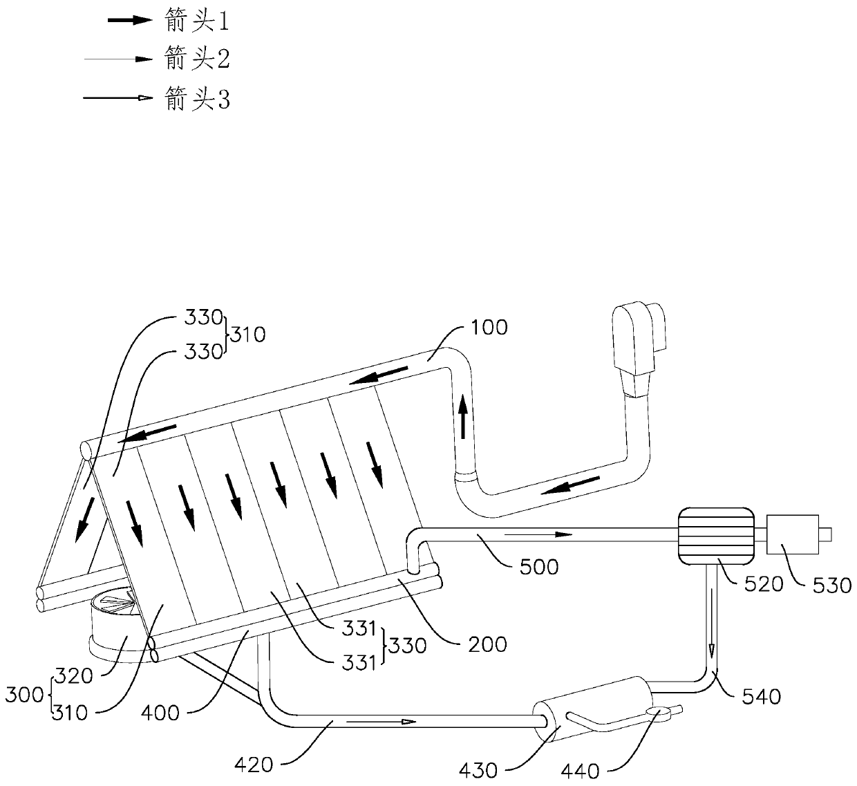
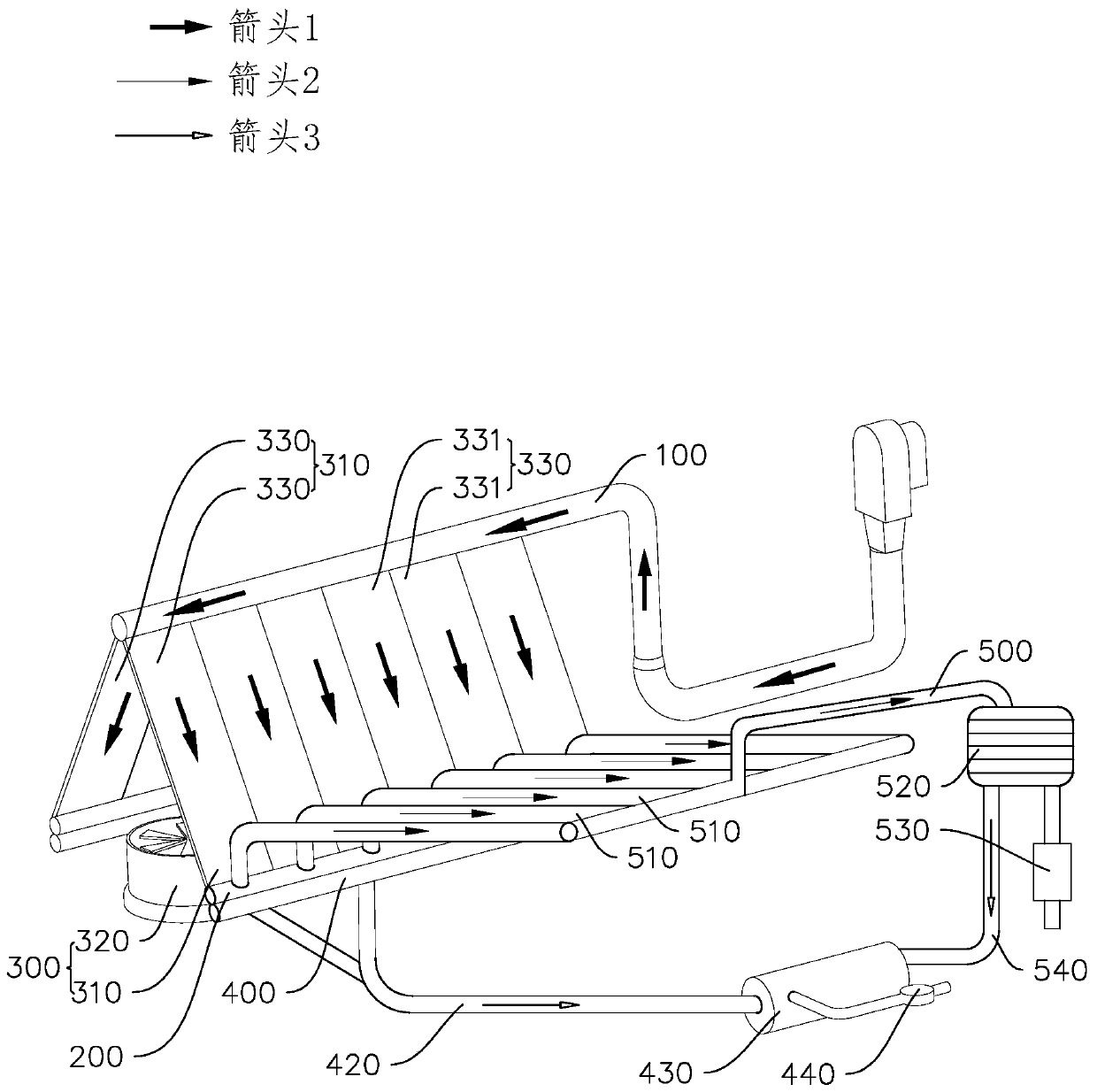
The invention discloses a series connection type air humidity mixed cooling system and an air cooling island system in order to solve the problems that in the thermal power generation field, pipelinebackpressure is high, and cooling efficiency is low. The series connection type air humidity mixed cooling system comprises a steam distribution pipeline, a water-steam separation pipeline, a co-flowair cooling heat radiator, a condensation water collection pipeline and a residual air collection pipeline. The invention further discloses a cooling method. The cooling method comprises the air cooling step and the water-steam separation step. The adverse flow area in a traditional air cooling island is omitted, the original adverse flow area is modified into a co-flow area, the heat transfer effect of the air cooling heat radiator is improved, and the resistance of the air cooling heat radiator is reduced; and the structure of the air cooling heat radiator is simplified, the air cooling heatradiator is only provided with a co-flow area pipe bundle, the resistance characteristic of the air cooling heat radiator is improved, and flow resistance distribution of the steam-water side is optimized.

Description

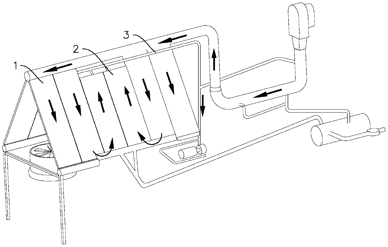
technical field [0001] The present invention relates to the field of thermal power generation, and further relates to the field of steam cooling of thermal power generation, in particular to a serial air-humidity mixed cooling system, an air-cooling island system and a cooling method. Background technique [0002] The air-cooled island system is an important part of the steam-water system of a thermal power plant. It is a mechanism that condenses the steam that has done work in the steam turbine 4 and keeps the steam turbine 4 vacuum through air cooling. [0003] Refer to attached figure 1 , the current common air-cooled island system includes a forward flow radiator 1 and a counterflow radiator 2 connected in series, the forward flow radiator 1 includes a number of parallel flow tube bundles, and the counterflow radiator 2 includes a number of parallel flow tube bundles The countercurrent tube bundle is blown by the axial fan to the two sets of radiators to cool the steam....

Claims


Application Information

Patent Timeline
Patent Type & Authority Applications(China)
IPC IPC(8): F28B1/06F28B9/02F28B9/08
CPCF28B1/06F28B9/08F28B9/10F28B11/00F22D11/06
Inventor 王卫良吕俊复王倩刘敏刘吉臻岳光溪
Owner JINAN UNIVERSITY
Learn More