
Fully automatic electrolytic polishing equipment

An electrolytic polishing and fully automatic technology, applied in electrolytic components, electrolytic process, etc., can solve the problems of low hourly output, high labor cost, difficult recruitment, etc., achieve the effect of strong clamping force, improve product quality, and prevent short circuit

Inactive Publication Date: 2018-10-23
湖北帕尔森机电设备有限公司
View PDF9 Cites 0 Cited by
  • Summary
  • Abstract
  • Description
  • Claims
  • Application Information

AI Technical Summary

Problems solved by technology

[0005] The purpose of the present invention is to overcome the problems of low hourly output, poor quality, difficult recruitment and high labor cost in the above-mentioned prior art, and propose a fully automatic electrolytic polishing equipment

Method used


Image

  • Fully automatic electrolytic polishing equipment
  • Fully automatic electrolytic polishing equipment

Examples


Embodiment 1

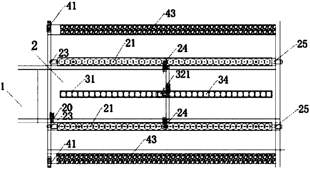
[0040] This embodiment provides a kind of automatic electrolytic polishing equipment, such as figure 1 and figure 2 As shown, it includes two sets of electrolysis tables 21, a primary conveyor belt 1, a secondary conveyor belt 2, a mechanical glove set 31, an overturning mechanism 25, two sets of cup inversion conveyor belts 43, a motor and a cleaning device. An anode plate platform 11 is provided on the electrolysis table 21, and a cathode rod 9 is arranged at a certain distance above the anode plate platform 11, and the polishing cup 12 is placed on the anode plate platform 11; After the control descends, it extends into the polishing cup 12 for a certain distance along the axis of the polishing cup 12 and does not contact the inner wall of the cup (to ensure that the cathode and anode will not be short-circuited during the electrolytic polishing process), and the electrolyte is passed through the polishing cup 12 at the same time. One end of the cathode rod 9 in the cup i...

Embodiment 2

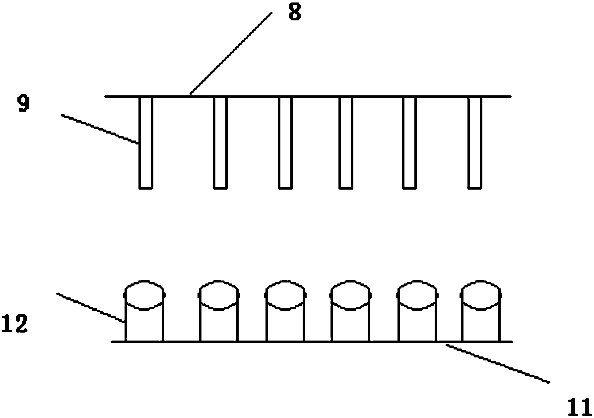
[0061] Such as figure 2 As shown, in the present embodiment, an anode plate platform 11 is provided on the electrolysis platform, a cathode plate 8 is arranged at a certain distance above the anode plate platform 11, and a plurality of cathode rods 9 are arranged on the cathode plate 8, and the polishing cup 12 is placed On the anode plate platform 11; the cathode plate 8 is connected to the lifting mechanism, and the cathode plate 8 is controlled by the lifting mechanism to ensure that multiple cathode rods 9 rise and fall at the same time and perform electrolytic polishing on multiple polishing cups 12. During electropolishing, a plurality of cathode rods 9 descend and extend into the polishing cup 12 for a certain distance along the axis of the corresponding polishing cup 12 and do not contact the inner wall of the cup (to ensure that the cathode and anode will not be short-circuited during the electropolishing process) , Electrolyte is injected into the cup body by stretc...


PUM

PropertyMeasurementUnit
lengthaaaaaaaaaa

Abstract

The invention provides full-automatic electropolishing equipment which comprises an anode plate platform, polishing cups placed on the anode plate platform and cathode bars arranged at a certain distance from the anode plate platform. In the electropolishing process, the polishing cups containing electrolyte are fixed to the anode plate platform, the cathode bars stretch into the corresponding polishing cups by a certain distance through moving devices along the axes of the polishing cups without making contact with the inner walls of cup bodies of the polishing cups, and then the anode plate platform and the cathode bars are electrified to electropolish the polishing cups. Since only the inner walls of the polishing cups are electropolished, the utilization rate of production resources is improved; and since it is ensured that the cathode bars can not make contact with the polishing cups, it is ensured that the cathode and the anode can not short-circuit, and the phenomenon that in the prior art, short-circuit occurs due to the fact that cathode bars are prone to making contact with products to be polished is avoided.

Description

technical field [0001] The invention relates to the technical field of machine processing, in particular to a fully automatic electrolytic polishing device with high output and high quality. Background technique [0002] Electrolytic polishing is to use the workpiece to be polished as the anode and the insoluble metal as the cathode. The two poles are immersed in the electrolytic cell at the same time, and the ionization reaction is carried out by direct current to produce selective anode dissolution, so as to remove fine burrs and increase the brightness of the workpiece surface. Effect. [0003] Most of the electrolytic polishing in the prior art adopts the semi-automatic production of electrolytic cells and purely manual electrolytic stations, and the output per hour is 250-300 pieces; the semi-automatic generation of electrolytic cells requires 4 operators, and manual clamping of parts is required. When the part is clamped before electropolishing, if the position betwee...

Claims


Application Information

Patent Timeline
Patent Type & Authority Patents(China)
IPC IPC(8): C25F7/00C25F3/16
CPCC25F3/16C25F7/00
Inventor 杨继芳
Owner 湖北帕尔森机电设备有限公司
Learn More