Color steel tile clamp with calibrating function based on lever principles

A lever principle, color steel tile technology, applied to roofs, roofs, buildings, etc. where tiles/slate tiles are used, it can solve the problems of easy oxidation and rust, difficult to remove screws, and not installed in place, etc., to enhance practicability and stability, simple and convenient operation, easy installation and disassembly

Inactive Publication Date: 2017-02-15
四川省科拓梦无人机科技有限公司
View PDF5 Cites 0 Cited by
  • Summary
  • Abstract
  • Description
  • Claims
  • Application Information

AI Technical Summary

Problems solved by technology

As we all know, screw clamping has good stability and has the advantage of being easy to install and disassemble. However, since the working environment of the roof clamp is on the roof, it is easy to get wet when it rains, and then it is easy to be oxidized and rusted, causing its The reduction of stability, and the rusted screws are usually difficult to disassemble, resulting in inconvenience of operation; in addition, the color steel tile roof fixture in the prior art is clamped and fixed by simple mechanical means, and it is not easy to use. With a calibration function, that is to say, the accuracy of the installation of the color steel tile roof fixture in the prior art usually depends on the experience of the staff to judge. Generally, people use whether the screws are tightened or not as the basis for judgment, but when When the screw is tilted or impurities appear between the clamping surfaces of the fixture, even if the screw is tightened, it does not mean that it is installed in place
Therefore, in summary, the use of screw clamping in the color steel tile roof fixture has the problem of not being installed in place, which leads to the risk that the color steel tile is easy to be blown off by strong winds

Method used


Image

  • Color steel tile clamp with calibrating function based on lever principles
  • Color steel tile clamp with calibrating function based on lever principles
  • Color steel tile clamp with calibrating function based on lever principles

Examples


Embodiment 1

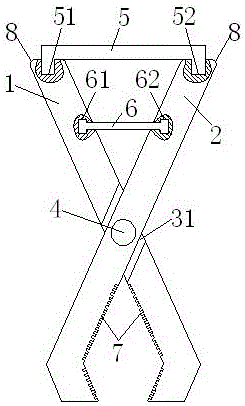
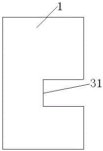
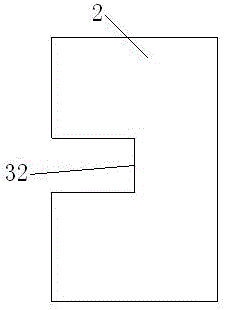
[0030] like figure 1 , figure 2 , image 3 , Figure 4 , Figure 5 , Image 6 As shown, in this embodiment, a color steel tile fixture based on the principle of leverage and with its own calibration function includes a hinge 4, a left splint 1 and a right splint 2 that are hinged together through the hinge 4, and also includes connecting the left splint 1 and the right splint 2 and a locking piece 5 for locking, and a calibration piece 6 connected between the left splint 1 and the right splint 2 and used for calibration.

[0031] The present invention adopts the principle of leverage, and uses the locking member 5 to lock the two left splints 1 and right splints 2 that are hinged together through the hinge 4, so that the present invention does not need to tighten the bolts during the installation and disassembly process, thus making the operation easier Convenience, the present invention also installs the calibration part 6 on the two splints. When the two splints are in...

Embodiment 2

[0033] This embodiment is further limited on the basis of Embodiment 1. In this embodiment, the upper end surface of the left splint 1 is provided with an A locking groove 51, and the upper end surface of the right splint 2 is provided with a B locking groove 52; The two ends of 5 are matched and installed in the A locking groove 51 and the B locking groove 52 respectively.

[0034] The locking member 5 in the present invention is installed in the locking groove provided on the two splints in a clamping manner, and the locking is realized by mutual restriction between the locking groove and the locking member 5. When installing, the user Clamping can be realized by snapping the locking piece 5 into the locking grooves of the two splints without the step of screwing, which makes the operation of the present invention more convenient, and the snap-fit ​​connection method is compared with the threaded connection More stable, thus enhancing the stability of the present invention. ...

Embodiment 3

[0037] This embodiment is further improved on the basis of Embodiment 1. In this embodiment, the side of the left splint 1 opposite to the right splint 2 is provided with an A positioning groove 61, and the right splint 2 corresponds to the A positioning groove 61. The position of B positioning groove 62 is set, and the two ends of the calibrating part 6 are matched and installed in A positioning groove 61 and B positioning groove 62 respectively.

[0038] The calibrating part 6 of the present invention is inserted into the positioning grooves provided on the two clamping blocks in the way of mortise joint. Using the above method, while realizing the connection, the calibration function can be realized, and the second locking effect can be realized, so that the present invention The installation and disassembly of the invention is more convenient, and the calibrating part 6 is used together with the locking part 5, which can enhance the stability of the present invention after ...


PUM


Abstract

The invention discloses a color steel tile clamp with a calibrating function based on lever principles. The color steel tile clamp comprises a hinge component (4), and a left clamping plate (1) and a right clamping plate (2) which are hinged together through the hinge component (4), and further comprises a locking component (5) and a calibrating component (6), wherein a locking groove A(51) is formed in the left clamping plate (1), and a locking groove B(52) is formed in the right clamping plate (2); the locking component (5) is mounted in the locking groove A(51) and the locking groove B(52); and a locating groove A(61) is formed in the left clamping plate (1), a locating groove B(62) is formed in the right clamping plate (2), and the two ends of the calibrating component (6) are separately mounted in the locating groove A(61) and the locating groove B(62) in a fit manner. By adopting the structure, the color steel tile clamp is simple in structure and low in manufacture cost. Compared with the prior art, the color steel tile clamp is higher in stability, higher in practicability and more convenient to mount and disassemble.

Description

technical field [0001] The invention relates to the technical field of roof installation, in particular, it is a color steel tile fixture based on the principle of leverage and with its own calibration function. Background technique [0002] In the roof design of modern buildings, metal seam roof is the most common design method. The so-called metal lock seam roof, which forms a lock seam perpendicular to the roof by locking adjacent panels together with each other through curling along the vertical edges of the panels. In this way, the panels are connected through metal lock seams to form a tightly connected and almost rigid roof system, which greatly enhances the tight connection between the panels and ensures the performance of roof sealing, waterproofing and heat preservation. [0003] And in the roof design of modern buildings, color steel tiles are more and more popular as a new type of building material, and they are cheaper than glazed tiles, so they are widely used...

Claims


Application Information

Patent Timeline
IPC IPC(8): E04D1/00E04D1/34
CPCE04D1/00E04D1/34E04D2001/3408
Inventor 金银龙
Owner 四川省科拓梦无人机科技有限公司
Why Eureka
Try Eureka