Supercharge Your Innovation With Domain-Expert AI Agents!

Pump and assembly method of the same

An assembly method and impeller technology, applied to pumps, components of pumping devices for elastic fluids, pump components, etc., can solve problems such as severe loss, complex processing, assembly, design, and durability issues

Active Publication Date: 2017-02-15
KUBOTA LTD
View PDF6 Cites 0 Cited by
  • Summary
  • Abstract
  • Description
  • Claims
  • Application Information

AI Technical Summary

Problems solved by technology

[0003] However, in this case, it is necessary to assemble the housing and the impeller in order to sandwich the sealing member in the annular gap, and in order to properly sandwich the sealing member in the annular gap, the dimensional accuracy of the impeller is required, and processing and assembly , more complex in design
In addition, the sealing member is attached to the gap between the outer peripheral surface of the suction port of the impeller and the casing, and strong friction occurs on the sealing member, and the wear caused by the rotational driving of the impeller is severe, and there is a problem in terms of durability.

Method used


Image

  • Pump and assembly method of the same
  • Pump and assembly method of the same
  • Pump and assembly method of the same

Examples


Embodiment Construction

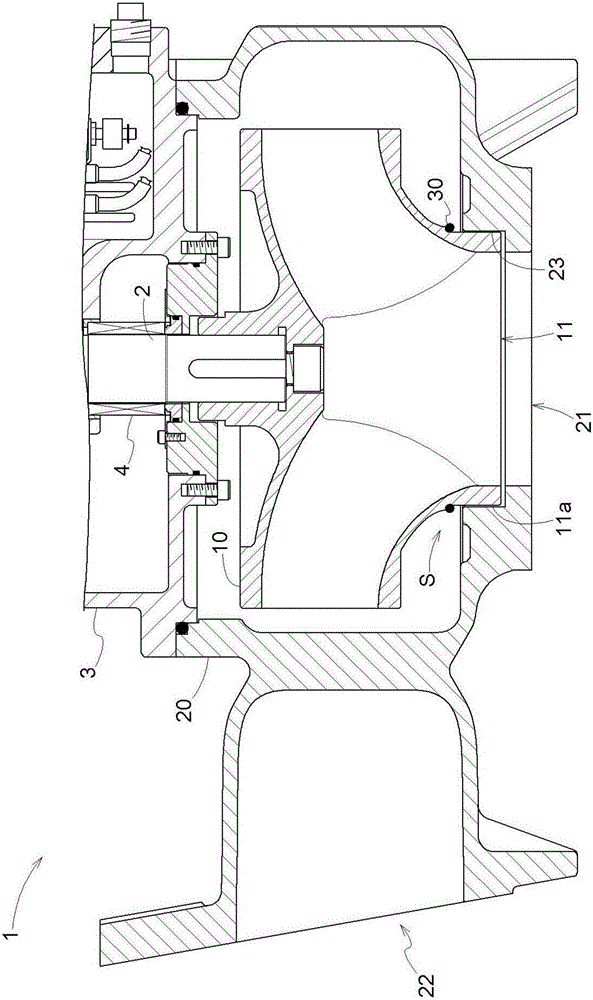
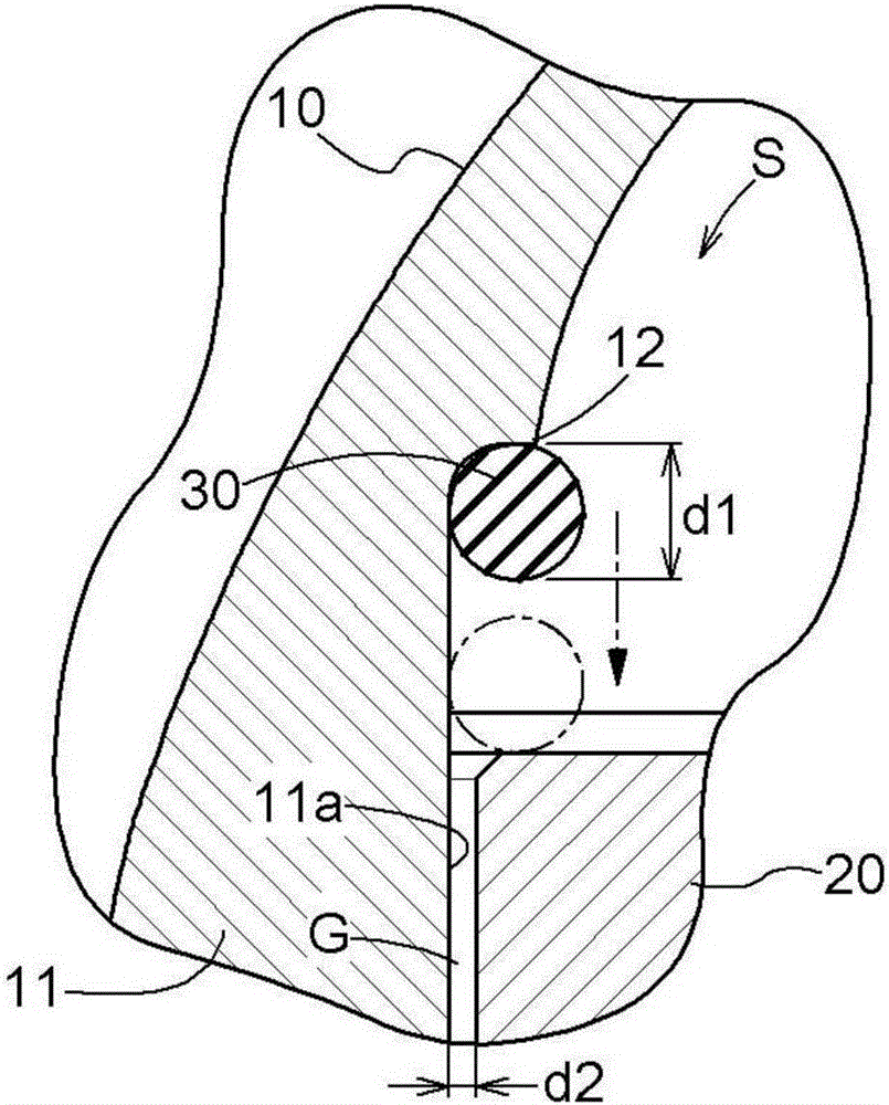
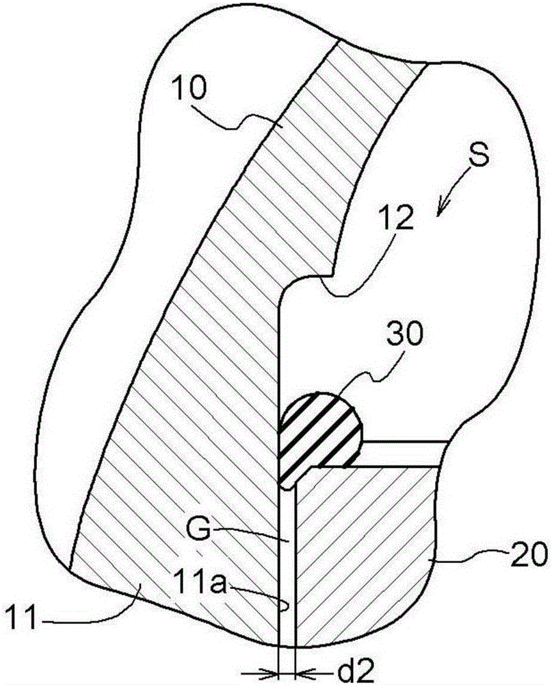
[0030] Embodiments of the pump and the method of assembling the pump according to the present invention will be described with reference to the drawings. The pump 1 of the present embodiment includes an impeller 10 and a pump housing 20 that accommodates the impeller 10 . In the pump 1 , an annular gap G is formed between the outer peripheral surface 11 a of the suction port 11 of the impeller 10 and the housing 20 . In addition, a sealing member 30 is provided on the outer peripheral surface 11a of the suction port 11 on the inner side of the casing 20 than the annular gap G, and the sealing member 30 is accommodated in the suction port so as to be movable in the axial direction into an open state and a closed state. 11, the open state is a state in which the sealing member 30 is separated from the annular gap G, and the closed state is a state in which the sealing member 30 moves from the open state to the annular gap G side to block the annular gap G. Thereby, assembly and...


PUM


Abstract

To provide a pump which prevents back flow of water to improve the pump efficiency while facilitating assembly and designing. A pump includes an impeller (10) and a casing (20) for storing the impeller (10). In the pump, an annular gap (G) is formed between an outer peripheral surface (11a) of a suction port (11) and the casing (20) in the impeller (10). The outer peripheral surface (11a), which is located at the inner side of the annular gap (G) with respect to the casing (20), includes a seal member (30). The seal member (30) is stored so as to move in an axial direction on the outer peripheral surface (11a) between an open state, in which the seal member (30) is separated from the annular gap (G), and a closed state, in which the seal member (30) is moved from the open state to the annular gap (G) side to close the annular gap (G).

Description

technical field [0001] The present invention relates to a pump including an impeller and a housing for accommodating the impeller, and an assembly method thereof. Background technique [0002] In the past, in such pumps, in order not to cause trouble in operation due to contact between the rotationally driven impeller and the casing, the outer peripheral surface of the suction port of the impeller and the casing are usually formed in a non-contact manner between them. A state in which an annular gap is formed. In addition, in this case, in order to prevent water from flowing backward from the high-pressure side of the rotationally driven impeller to the low-pressure side through the annular gap, the annular gap sandwiches the sealing member without creating a gap, thereby preventing backflow and improving pump efficiency. Improvement (for example, refer to the specification of Chinese Utility Model Publication No. 200949545 (Patent Document 1)). [0003] However, in this c...

Claims


Application Information

Patent Timeline
Patent Type & Authority Applications(China)
IPC IPC(8): F04D29/08F04D29/60
CPCF04D29/086F04D29/605
Inventor 西川正洋桝谷英俊荒木慎一郎桥本靖志
Owner KUBOTA LTD
Features
  • R&D
  • Intellectual Property
  • Life Sciences
  • Materials
  • Tech Scout
  • Unparalleled Data Quality
  • Higher Quality Content
  • 60% Fewer Hallucinations
Learn More