
Heat dissipation fan blade structure and heat dissipation fan

A heat dissipation fan and fan blade technology, which is applied to non-variable pumps, pump components, components of pumping devices for elastic fluids, etc., can solve problems such as reducing fan characteristics, increasing noise, and unstable fan flow field

Active Publication Date: 2021-10-08
ASIA VITAL COMPONENTS SHENZHEN CO LTD
View PDF7 Cites 0 Cited by
  • Summary
  • Abstract
  • Description
  • Claims
  • Application Information

AI Technical Summary

Problems solved by technology

[0002] like figure 1 As shown, the end 111 of each fan blade 11 of the known axial flow fan 10 is different from the pressure distribution on the upper surface 112 and the lower surface 113, causing the airflow to roll from the high-pressure lower surface 113 to the low-pressure upper surface 112. The end 111 generates a strong end vortex 12, and the end vortex 12 causes the fan flow field to be unstable, which increases noise and reduces fan performance

Method used


Image

  • Heat dissipation fan blade structure and heat dissipation fan
  • Heat dissipation fan blade structure and heat dissipation fan
  • Heat dissipation fan blade structure and heat dissipation fan

Examples


Embodiment Construction

[0044] The above-mentioned purpose of the present invention and its structural and functional characteristics will be described based on the preferred embodiments of the accompanying drawings.

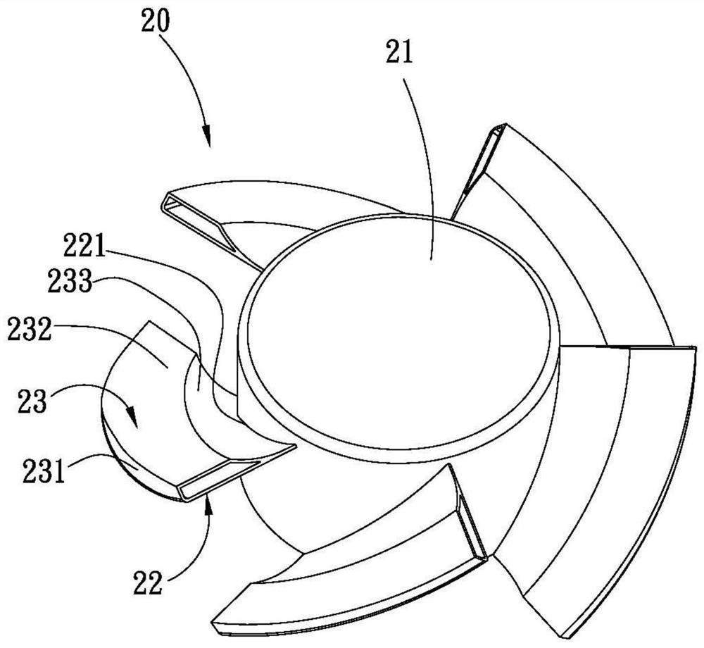
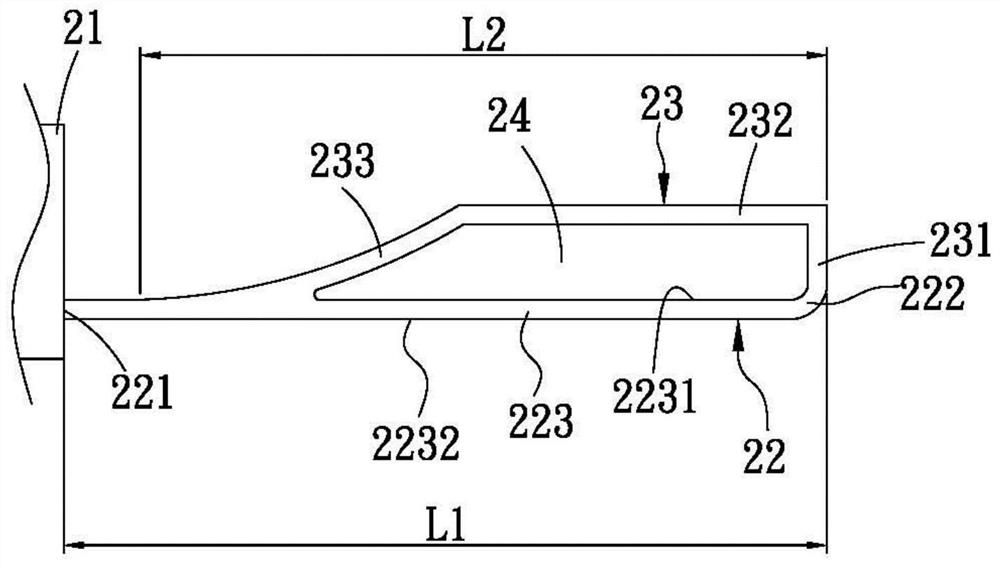
[0045] Please refer to figure 2 It is a three-dimensional schematic diagram of a cooling fan with a cooling blade structure according to the present invention; Figure 3A A cross-sectional schematic diagram of an annular structure for a cooling fan blade structure; Figure 3B-3E It is a cross-sectional schematic diagram of an alternative implementation of the annular structure of the cooling fan blade structure. As shown in the figure, the cooling fan 20 of the present invention includes a hub 21 and a plurality of main fan blades 22 . The main fan blades 22 are arranged around the outer side of the hub 21, each main fan blade 22 has a root portion 221 and an end portion 222, and the root portion 221 and the end portion 222 are respectively arranged on opposite ends of the main fan ...


PUM


Abstract

The invention provides a cooling fan blade structure and a cooling fan thereof, which include a main fan blade and an auxiliary fan blade. The main fan blade has a root portion and an end portion, the root portion is connected to a hub, the end portion radially extends toward the opposite direction of the hub, and a body portion is formed between the root portion and the end portion. The auxiliary fan blade extends from the end toward the root of the main fan blade to the main body and forms an annular structure with the main fan blade, and the annular structure defines a flow passage between the main fan blade and the auxiliary fan blade .

Description

【Technical field】 [0001] The invention relates to the field of cooling fans, in particular to a cooling fan blade structure and a cooling fan with the cooling fan blade structure. 【Background technique】 [0002] Such as figure 1 As shown, the end 111 of each fan blade 11 of the known axial flow fan 10 is different from the pressure distribution on the upper surface 112 and the lower surface 113, causing the airflow to roll from the high-pressure lower surface 113 to the low-pressure upper surface 112. The end 111 generates a strong end vortex 12 , and the end vortex 12 causes the flow field of the fan to be unstable, thereby increasing noise and reducing the performance of the fan. [0003] Therefore, how to reduce the vortex at the end of the fan when it is running, and how to reduce the operating noise and improve the air pressure and air volume characteristics are the goals that designers in this field should strive to improve. 【Content of invention】 [0004] Therefor...

Claims


Application Information

Patent Timeline
Patent Type & Authority Patents(China)
IPC IPC(8): F04D29/38F04D29/32F04D29/66
CPCF04D29/325F04D29/384F04D29/388F04D29/666
Inventor 陈佑慈王仲澍
Owner ASIA VITAL COMPONENTS SHENZHEN CO LTD
Learn More