Eureka AIR delivers breakthrough ideas for toughest innovation challenges, trusted by R&D personnel around the world.

Hubbed flange

A flange and neck technology, which is applied in the field of neck flanges, can solve problems such as unqualified flanges, operation accidents, and gaps, and achieve the effects of stable connection, stable structure, and good sealing effect

Inactive Publication Date: 2017-02-15
田玉
View PDF6 Cites 0 Cited by
  • Summary
  • Abstract
  • Description
  • Claims
  • Application Information

AI Technical Summary

Problems solved by technology

[0002] Existing neck flanges generally use welding to connect the neck to the top, but if such a connection method is not welded well, it is easy to break or there is a gap. Intelligent rework, if the inspection is not careful and sold, it may cause an operation accident, and many places in the welding place are unevenly stressed, and it is likely to break from some weak places

Method used


Image

  • Hubbed flange
  • Hubbed flange

Examples


Embodiment Construction

[0015] In order to make the technical means, creative features, goals and effects achieved by the present invention easy to understand, the present invention will be further described below in conjunction with specific embodiments.

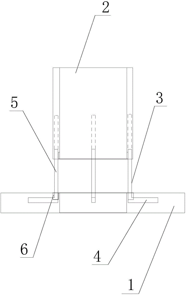
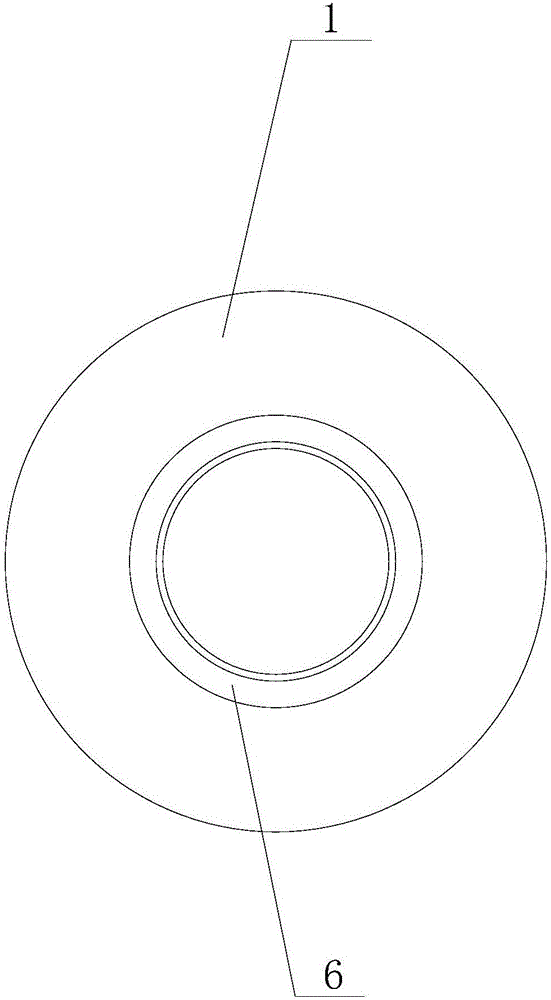
[0016] Such as figure 1 and figure 2 As shown, a necked flange includes a flange body 1 and a pipe neck 2, the pipe neck 2 is fixed directly above the flange body 1, and also includes a number of "L" shaped reinforcing rods 3, the reinforcing The cross bar 4 of the bar 3 is located inside the flange body 1, the vertical bar 5 of the reinforcing bar 3 is located inside the pipe neck 2, and the reinforcing bar 3 is evenly arranged in the flange body 1 and the pipe neck 2, and the pipe neck 2 is provided with a circle of depressions on the inner wall of the connection end of the flange body 1, and a concave annular groove 6 is provided on the flange body 1 corresponding to the connection part of the pipe neck 2, and the annular groove 6 is recessed...


PUM


Abstract

The invention relates to a hubbed flange. The hubbed flange comprises a flange body and a pipe neck. The pipe neck is fixedly arranged over the flange body. The hubbed flange is characterized by further comprising a plurality of L-shaped strengthening rods, transverse rods of the strengthening rods are located in the flange body, vertical rods of the strengthening rods are located in the pipe neck, and the strengthening rods are evenly arranged in the flange body and the pipe neck; the inner wall of the end, connected with the flange body, on the pipe neck is subject to one-circle concave arrangement, and the position, corresponding to the pipe neck connecting part, of the flange body is provided with a concave annular groove; the annular groove is matched with the bottom concave arrangement part of the pipe neck in size; and the bottom concave part of the pipe neck is arranged in the annular groove in a sleeved manner. According to the hubbed flange, the flange body and the pipe neck are connected and reinforced through the strengthening rods, so that connection is more stable; the multiple strengthening rods are evenly arranged so that an overall structure can be more stable, and performance defects caused by one part cannot happen; and the bottom concave part of the pipe neck is arranged in the annular groove in the sleeved manner so that the sealing effect can be better, and the structure at the connecting position is more stable.

Description

technical field [0001] The invention relates to a flange, especially a flange with a neck. Background technique [0002] Existing neck flanges generally use welding to connect the neck to the top, but if such a connection method is not welded well, it is easy to break or there is a gap. Smart rework, if not carefully tested and sold, may cause operational accidents, and many places in the welding place are unevenly stressed, and it is likely to break from some weak places. Contents of the invention [0003] Aiming at the deficiencies in the prior art, the invention provides a necked flange with a structurally stable neck joint. [0004] In order to achieve the above object, the present invention is achieved through the following technical solutions: [0005] A flange with a neck, including a flange body and a pipe neck, the pipe neck is fixed directly above the flange body, and is characterized in that it also includes a number of "L" shaped reinforcing rods, the cross b...

Claims


Application Information

Patent Timeline
Patent Type & Authority Applications(China)
IPC IPC(8): F16L23/00F16L23/16
CPCF16L23/00F16L23/162
Inventor 田玉
Owner 田玉
Why Eureka
Eureka Blog
Learn More