Refractive index measurement method

A technology of refractive index and incident surface, applied in the field of measuring refractive index, which can solve the problems of low accuracy and large error of refractive index

Active Publication Date: 2017-02-15
HUBEI NEW HUAGUANG NEW INFORMATION MATERIALS CO LTD
View PDF4 Cites 8 Cited by
  • Summary
  • Abstract
  • Description
  • Claims
  • Application Information

AI Technical Summary

Problems solved by technology

[0003] In the prior art, the method of measuring the refractive index of optical materials is usually to measure the incident angle and exit angle when light passes through a certain surface of the optical material, and then obtain the refractive index of the optical material ...

Method used


Image

  • Refractive index measurement method
  • Refractive index measurement method
  • Refractive index measurement method

Examples


Embodiment 1

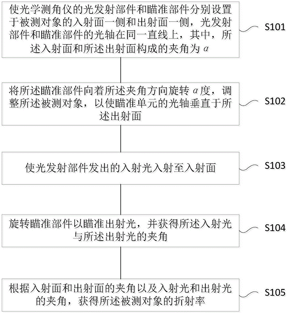
[0026] figure 1 A flowchart showing a method for measuring a refractive index according to an embodiment of the present invention. Such as figure 1 As shown, the method mainly includes:

[0027] Step 101, arrange the light emitting part and the aiming part of the optical goniometer on the incident surface side and the outgoing surface side of the measured object respectively, the optical axes of the light emitting part and the aiming part are on the same straight line, wherein the The angle formed by the incident surface and the outgoing surface is α;

[0028] Step 102, rotating the aiming component α degrees toward the included angle direction, and adjusting the measured object so that the optical axis of the aiming unit is perpendicular to the exit surface;

[0029] Step 103, making the incident light emitted by the light-emitting component incident on the incident surface;

[0030] Step 104, rotating the aiming component to aim at the outgoing light, and obtaining the...


PUM


Abstract

The invention relates to a refractive index measurement method which comprises the steps: a light emission component and an aiming component of an optical angle gauge are arranged on the incident plane side and the emergent plane side of an object to be measured respectively, the optical axis of the light emission component and the optical axis of the aiming component are arranged on the same straight line, and the included angle between the incident plane and the emergent plane is alpha; the aiming component is rotated at by the alpha degree in the included angle direction, and the object to be measured is adjusted to enable the optical axis of the aiming component to be perpendicular to the emergent plane; the incident light emitted by the light emission component irradiates to the incident plane; the aiming component is rotated to be aligned at to the emergent light, and the included angle beta between the incident light and the emergent light is obtained; the refractive index n of the object to be measured can be obtained according to the included angle alpha between the incident plane and the emergent plane and the included angle beta between the incident light and the emergent light. By means of the aiming component of the optical angle gauge, the incident light can perpendicularly irradiate into the incident plane of the object to be measured at an accurate angle; then the included angle between the incident light and the emergent light can be obtained by rotating the aiming component; thus, the accuracy of the finally-obtained refractive index of the object to be measured can be higher.

Description

technical field [0001] The invention relates to the field of precision measurement of optical materials, in particular to a method for measuring the refractive index. Background technique [0002] The refractive index parameters of optical materials are the basis of optical design. Only by accurately mastering the reliable data of the refractive index of optical materials can high-quality design work be completed according to requirements. Moreover, for optical material research and manufactures, determining the refractive index performance index of the optical material under study is an important basic content, the technical basis for material evaluation, and the reference basis for production finalization. Therefore, the refractive index of optical materials The accurate determination of is an important prerequisite for the use and development of optical materials. [0003] In the prior art, the method of measuring the refractive index of optical materials is usually to m...

Claims


Application Information

Patent Timeline
IPC IPC(8): G01N21/41
CPCG01N21/4133G01N2021/4153
Inventor 张庆何蓉杨谧玲邬理凡王德国
Owner HUBEI NEW HUAGUANG NEW INFORMATION MATERIALS CO LTD
Why Eureka
Try Eureka