
Low power consumption control method for pressure-sensitive key identification device

A technology for identifying devices and control methods, which is applied in the direction of instruments, electrical digital data processing, digital data processing components, etc., can solve problems such as high power consumption, achieve the effects of reducing power consumption, high response speed, and ensuring user experience

Inactive Publication Date: 2017-02-15
CHIPSEA TECH SHENZHEN CO LTD
View PDF6 Cites 6 Cited by
  • Summary
  • Abstract
  • Description
  • Claims
  • Application Information

AI Technical Summary

Problems solved by technology

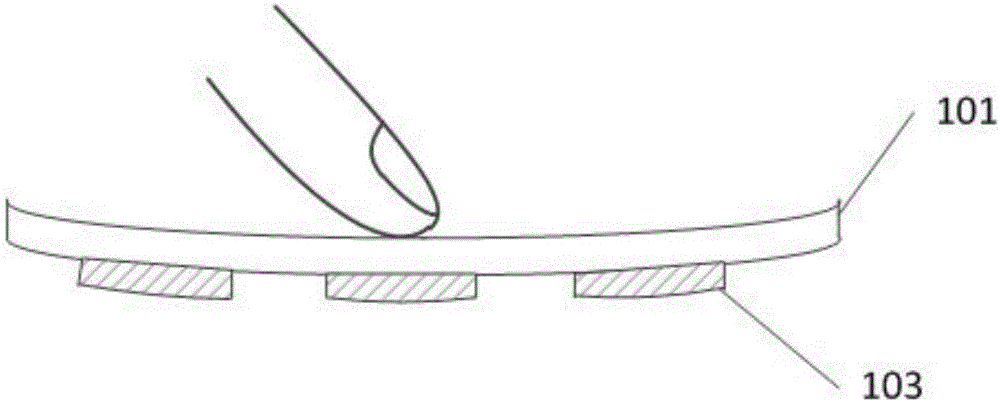
[0007] Based on this, the purpose of the present invention is to provide a low power consumption control method for a pressure-sensitive key recognition device, so as to solve the problem of high power consumption when the terminal equipment uses pressure-sensitive keys

Method used


Image

  • Low power consumption control method for pressure-sensitive key identification device
  • Low power consumption control method for pressure-sensitive key identification device
  • Low power consumption control method for pressure-sensitive key identification device

Examples


Embodiment 1

[0049] Such as Figure 4 As shown, in this embodiment, it is assumed that the key panel is provided with 6 keys.

[0050] Set two working modes: normal working mode and low power consumption working mode, the working state transition diagram is as follows figure 1 shown.

[0051] Assume that the preset time threshold is 5 seconds and the trigger threshold is x.

[0052] Assume that the high switching frequency is 100Hz, and the low switching frequency is 50Hz (the high frequency (high switching frequency) is usually a frequency above 100Hz. In actual use, it is generally 100hz~150hz, and the typical value is 100hz; the low frequency (low switching frequency) is usually The frequency below 50Hz is generally 30hz~50hz in actual use, and the typical value is 50hz).

[0053] The buttons are numbered sequentially from left to right, and the parity of the installation serial number is grouped. Button "1", button "3" and button "5" are button 1 group, button "2", button "4" and bu...

Embodiment 2

[0066] The main difference between this embodiment and the first embodiment is that the low power consumption working mode can be divided into two levels.

[0067] This embodiment assumes that the button panel is provided with 6 buttons, such as Figure 4 shown.

[0068] Set three working modes: normal working mode, low-power working mode 1 and low-power working mode 2, the working state transition diagram is as follows Figure 9 shown.

[0069] Assume that the preset time threshold 1 is 5 seconds, the time threshold 2 is 10 seconds, and the trigger threshold is x.

[0070] Assume a high transition frequency of 100Hz and a low transition frequency of 50Hz.

[0071] The buttons are numbered sequentially from left to right, and the parity of the installation serial number is grouped. Button "1", button "3" and button "5" are button 1 group, button "2", button "4" and button "6" There are 2 groups of buttons.

[0072] The normal working mode processing flow is as follows: ...


PUM


Abstract

The invention discloses a low power consumption control method for a pressure-sensitive key identification device. The method is characterized in that two working modes, i.e., a normal working mode and a low power consumption working mode, are defined; two comparison thresholds, i.e., a time threshold and a trigger threshold, are set; when the duration of the absence of a trigger signal for keys is longer than the time threshold, the device enters the low power consumption working mode; and when a pressure is detected to exceed the trigger threshold, the device enters the normal working mode. The method provided by the invention has the advantages that through power consumption control of the keys in the different working statuses, the working power consumption of the key device is reduced, a higher response speed is maintained, and good use experience of users is ensured.

Description

technical field [0001] The invention belongs to the field of touch technology, and in particular relates to a low power consumption control method of a pressure-sensitive key. Background technique [0002] In the field of electronic products, button technology has a wide range of applications. As controllable devices, for example, televisions, microwave ovens, range hoods, etc. in household appliances, mobile phones, digital cameras, e-readers, etc. in personal digital devices, there are more or less key devices on these devices. [0003] At present, most terminal devices use mechanical switch buttons, which use the principle of circuit conduction. When the button is pressed, the conductor material contacts the circuit to make the circuit conduction. When the button is released, the conductor material moves away from the circuit to make the circuit open. Disconnect, so as to realize the "switch" command of the button. With the increasing demand of consumers, the disadvanta...

Claims


Application Information

Patent Timeline
Patent Type & Authority Applications(China)
IPC IPC(8): G06F1/32
CPCG06F1/325
Inventor 梁时廖文忠
Owner CHIPSEA TECH SHENZHEN CO LTD
Learn More