Power amplifier control system and method based on automatic level control

An automatic level and control system technology, applied in electrical components, transducer circuits, sensors, etc., can solve the problems of wasting power amplifier performance, excessive power drop, unable to protect power amplifier in time, etc., to reduce working power consumption, The effect of reducing power consumption

An automatic level and control system technology, applied in electrical components, transducer circuits, sensors, etc., can solve the problems of wasting power amplifier performance, excessive power drop, unable to protect power amplifier in time, etc., to reduce working power consumption, The effect of reducing power consumption

CN110351630AActive Publication Date: 2019-10-18SUNWAVE COMM

Image

  • Power amplifier control system and method based on automatic level control
  • Power amplifier control system and method based on automatic level control
  • Power amplifier control system and method based on automatic level control

Examples


Embodiment 1

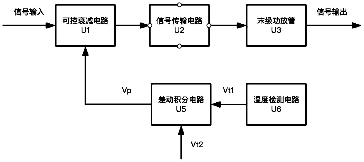
[0049] Embodiment 1: as attached figure 1 , 3 As shown, a power amplifier control system based on automatic level control includes a controllable attenuation circuit U1, a signal transmission circuit U2, a final power amplifier tube U3, a temperature detection circuit U6, and a differential integration circuit U5, wherein the controllable attenuation circuit U1 The first input terminal of the signal transmission circuit U2 is connected to the signal input, the second input terminal is connected to the output signal Vp of the differential integration circuit U5; the output terminal is connected to the signal transmission circuit U2; the input terminal of the signal transmission circuit U2 is connected to the controllable attenuation circuit U1, and the output terminal is connected to the terminal The first-stage power amplifier tube U3; the input end of the final-stage power amplifier tube U3 is connected to the output end of the signal transmission circuit U2, and the output e...

Embodiment 2

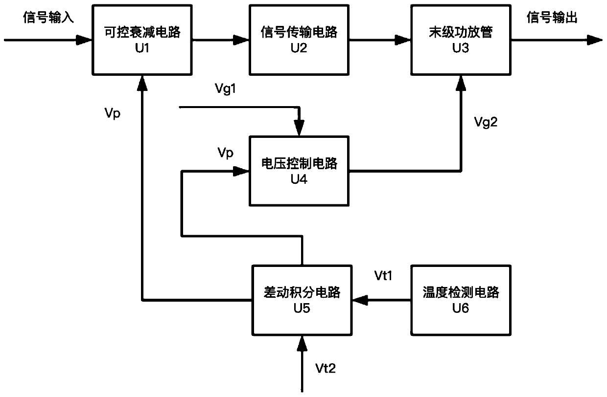
[0076] Embodiment 2: as figure 2 As shown, on the basis of Embodiment 1, a voltage control circuit U4 is also included. The first input port of the voltage control circuit U4 is connected to the standard voltage Vg1, and the second input port is connected to the output port of the differential integration circuit U5 to receive the control signal Vp; The output port of the voltage control circuit U4 is connected to the power input port of the final power amplifier tube U3; the power port of the final power amplifier tube is connected to the output signal Vg2 of the voltage control circuit U4.

[0077] In this embodiment, the voltage control circuit U4 has the interchangeability of digital circuits and analog circuits, such as Figure 4 As shown, the voltage control circuit in the form of a digital circuit includes ADC, DAC, single-chip microcomputer Q5 and two input signals Vp and Vg1; where Vp is the output control signal of the differential integration circuit; Vg1 is the co...


PUM


Abstract

The invention discloses a power amplifier control system and a method based on automatic level control. The device mainly comprises a controllable attenuation circuit and the like. A first input end of the controllable attenuation circuit is connected with signal input, a second input end of the controllable attenuation circuit is connected with an output control signal Vp of a differential integrating circuit, an output end of the controllable attenuation circuit is connected with an input end of a signal transmission circuit, an output end of the signal transmission circuit is connected withan input end of the final-stage power amplifier tube, and an output end of the final-stage power amplifier tube is signal output; a temperature detection circuit is used for detecting the temperatureof the power amplifier. A voltage control circuit can be added to reduce the static power consumption of the power amplifier tube. The power amplifier has the beneficial effects that the power consumption is reduced by adopting a method of reducing the static power consumption of the power amplifier tube besides a method of reducing the power, and finally, the minimum output power and the power amplifier power consumption under the minimum static state are very small, so that the power amplifier can keep certain power output under an extreme high-temperature condition, and the system keeps apart of communication functions.

Description

technical field [0001] The invention relates to the field of power amplifier systems, in particular to a power amplifier control system and method based on automatic level control. Background technique [0002] Power amplifiers are widely used in electronic products such as communications and home appliances. They are mainly used to amplify high-power signals, increase signal strength, and improve signal coverage. With market demand and technological progress, the size of various electronic products is increasing. The smaller the power amplifier, the more complex the heat dissipation environment of the power amplifier will be, and the performance of the equipment will be seriously degraded or even damaged due to the high temperature of the equipment. [0003] The protection measures for the power amplifier of the existing products are usually when the temperature of the power amplifier module is detected to be higher than the preset threshold temperature, the power amplifier...

Claims


Application Information

Patent Timeline
18 Oct 2019
Publication
CN110351630A
IPC
H04R3/00
CPC
H04R3/00; H04R2420/05
Inventors
俞利光; 雷文平