Structurally-improved remote controller

An improved remote control technology, applied in the field of remote control, can solve the problems of easy to wear and jam, the confirmation key is easy to shift, and the indicator light can not play a good light prompting function, so that the visual prompt is clearly clear and the experience is felt. Better, Reduced Interference Effects

Inactive Publication Date: 2017-02-15
SMK ELECTRONICS (DONGGUAN) CO LTD
View PDF8 Cites 4 Cited by
  • Summary
  • Abstract
  • Description
  • Claims
  • Application Information

AI Technical Summary

Problems solved by technology

[0003] In order to increase the practicability of the remote control, the remote control often includes a direction selection key and a confirmation key, and the confirmation key is located in the middle of the direction selection key, but in practical applications, due to the high frequency of use of the confirmation key and the direction selection key, After using for a period of time, it is easy to wear and jam between the confirmation key and the direction selection key or between the direction selection key and the shell, and the position of the confirmation key is prone to shift, and cannot be located in the center of the direction selection key, which will affect the remote control when in use. experience feeling
[0004] In addition, the indicator light is a very commonly used component on the remote control. At present, the common SMD LED on the market is often used to realize the light indication function. However, due to the limitation of the structure of the SMD LED light, its light-emitting part is located on the circuit board , there is a certain distance from the shell, coupled with the interference of natural light in the environment, the indicator light on the remote control cannot play a good light prompt function, and the defect is obvious

Method used


Image

  • Structurally-improved remote controller
  • Structurally-improved remote controller
  • Structurally-improved remote controller

Examples


Embodiment Construction

[0022] In order to facilitate the understanding of those skilled in the art, the present invention will be further described below in conjunction with the examples, and the contents mentioned in the embodiments are not intended to limit the present invention.

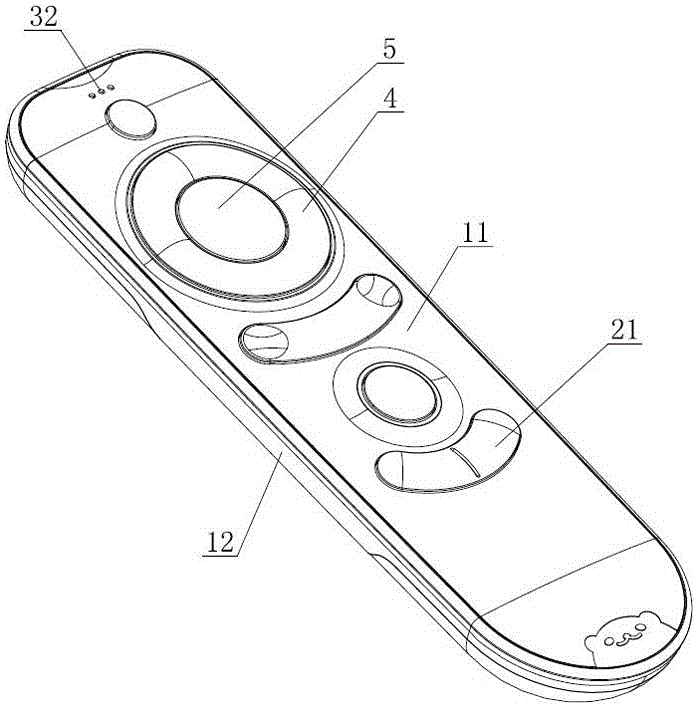
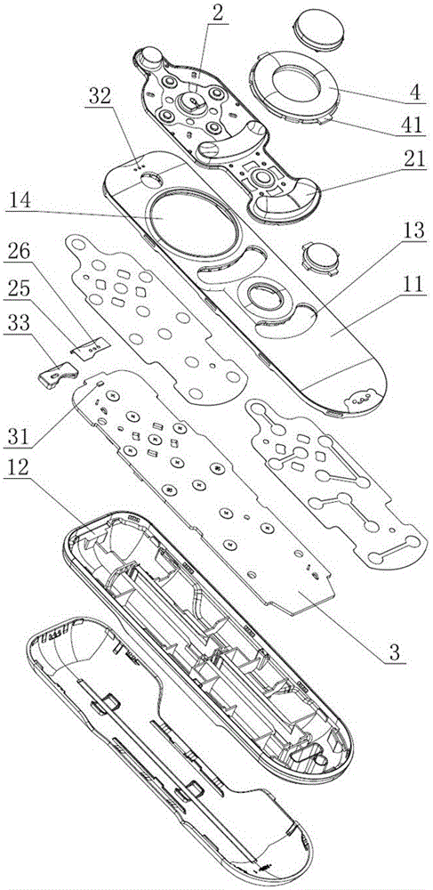
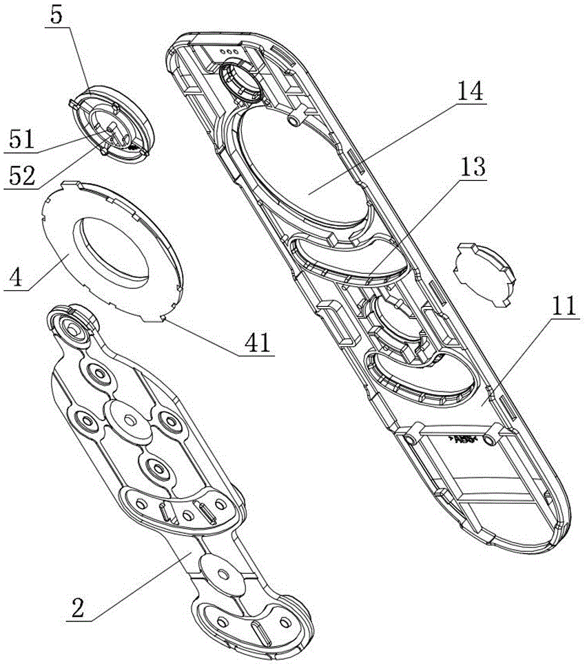
[0023] like Figure 1 to Figure 3 As shown, a structure-improved remote control includes an upper casing 11, a lower casing 12, and a soft rubber panel 2. A circuit board 3 is arranged under the soft rubber panel 2, and an indicator light is arranged at the front of the circuit board 3. 31, the front end of the upper housing 11 is provided with a number of first light holes 32 corresponding to the positions of the indicator lights 31, the soft rubber panel 2 is provided with a plurality of soft rubber buttons 21, and the upper housing 11 is provided with A plurality of button holes 13 corresponding to the soft rubber buttons 21 one by one, the soft rubber buttons 21 are movably embedded in the button holes 13, the upper...


PUM


Abstract

The invention relates to the technical field of a remote controller, and particularly relates to a structurally-improved remote controller. The structurally-improved remote controller comprises an upper shell, a lower shell, a flexible glue panel, a circuit board, a first light hole, flexible glue keys, key holes, a main key hole, a hard UDLR (Up, Down, Left, Right) key and a center connection part; the center connection part is fixedly connected with a hard center key; the hard center key is positioned in a center hole of the hard UDLR key; a clamping position for preventing separation of the hard UDLR key from the upper shell is formed on the outer edge of the hard UDLR key; a light blocking layer structure is arranged at the upper part of the flexible glue panel and close to the position of an indication lamp; the light blocking layer structure is provided with a second light hole corresponding to the position of the first light hole. The invention provides the structurally-improved remote controller which is high in centering and still can keep flexible pressing and touch of the keys after being used for a long time; a surface-mounted LED can be used as the indication lamp; the structurally-improved remote controller has the advantage of preventing interference of natural light to light display.

Description

technical field [0001] The invention relates to the technical field of remote controllers, in particular to a structurally improved remote controller. Background technique [0002] Radio remote control (RF Remote Control) is a remote control device that uses radio signals to control various institutions in the distance. After these signals are received by the remote receiving equipment, they can instruct or drive other corresponding mechanical or electronic equipment to complete various operations, such as closing the circuit, moving the handle, and starting the motor, and then these machines perform the required operations. As a kind of remote control complementary to infrared remote control, it has been widely used in the fields of household appliances, garage doors, electric doors, barrier gate remote control, burglar alarm, industrial control and wireless smart home. [0003] In order to increase the practicability of the remote control, the remote control often include...

Claims


Application Information

Patent Timeline
Patent Type & Authority Applications(China)
IPC IPC(8): G08C17/02
CPCG08C17/02
Inventor 杉本刚平
Owner SMK ELECTRONICS (DONGGUAN) CO LTD
Why Eureka
Try Eureka