
Method and power supply device for balanced output voltage of power supplies connected in parallel

A technology of output voltage and power supply device, applied in the field of power supply, which can solve the problems of different output voltage of constant voltage power supply, power backflow, parallel operation of different output voltage of constant voltage power supply, etc., and achieve the effect of improving stability and use efficiency

Active Publication Date: 2020-06-16
SHENZHEN EX LIGHTING TECH HLDG
View PDF5 Cites 0 Cited by
  • Summary
  • Abstract
  • Description
  • Claims
  • Application Information

AI Technical Summary

Problems solved by technology

[0002] In the traditional design of outdoor power supply, a constant voltage power supply group is usually used to supply power to electrical equipment. In order to meet the power supply requirements of the load, the constant voltage power supply group is usually composed of multiple constant voltage power supplies in series. The service life and damage of each constant-voltage power supply in the piezoelectric power supply group are different, and the output voltage of each constant-voltage power supply is different, which cannot meet any power demand of the user; and the traditional constant-voltage power supply cannot be used directly due to the different output voltages. Parallel operation is easy to cause backflow and damage to the power supply with low output voltage; or use a balance device to balance the output voltage of each power supply, but the number of power supplies that can be connected in parallel in this way is limited, and the balance device will bring additional costs lead to increased costs

Method used


Image

  • Method and power supply device for balanced output voltage of power supplies connected in parallel
  • Method and power supply device for balanced output voltage of power supplies connected in parallel
  • Method and power supply device for balanced output voltage of power supplies connected in parallel

Examples


Embodiment Construction

[0047] The present application will be described in further detail below in conjunction with the accompanying drawings and specific embodiments. It should be understood that the following exemplary embodiments and descriptions are only used to explain the present invention, not as a limitation to the present invention, and, in the case of no conflict, the embodiments in the application and the features in the embodiments can be combined with each other .

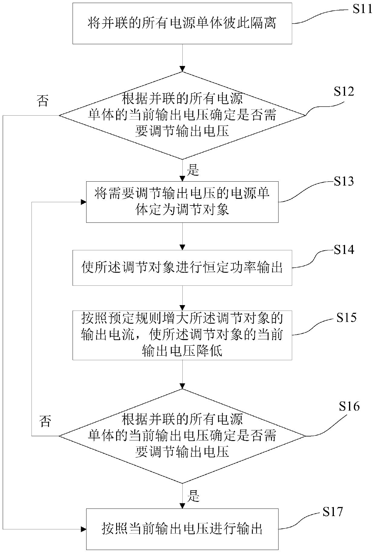
[0048] Such as figure 1 As shown, the embodiment of the present invention provides a method for equalizing the output voltage of parallel power supplies, including:

[0049] Step S11, isolating all power supply units connected in parallel from each other;

[0050] Step S12, determine whether the output voltage needs to be adjusted according to the current output voltages of all power supply units connected in parallel, if yes, go to step S13, if not, go to step S17;

[0051] Step S13, setting the power supply unit whose o...


PUM


Abstract

Embodiments of the present invention provide a method for equalizing the output voltage of parallel power supplies and a power supply device. The method includes: S11, isolating all power supply units connected in parallel from each other; S12, determining whether to It is necessary to adjust the output voltage, if yes, skip to S13, if not, skip to S17; S13, set the power unit whose output voltage needs to be adjusted as the adjustment object; S14, make the adjustment object output constant power; S15, increase the power according to the predetermined rule Increase the output current of the adjustment object to reduce the current output voltage of the adjustment object; S16, determine whether the output voltage needs to be adjusted according to the current output voltage of all power supply units connected in parallel, if not, restore the parallel connection of all power supply units And go to S17, if yes, jump back to S13; S17, output according to the current output voltage. The embodiments of the present invention enable the power supply units to be directly used in parallel to meet different power requirements in different occasions and improve the stability of the power supply device.

Description

technical field [0001] The invention relates to the technical field of power supplies, in particular to a method and a power supply device for equalizing the parallel output voltage of power supplies. Background technique [0002] In the traditional design of outdoor power supply, a constant-voltage power supply group is usually used to supply power to electrical equipment. In order to meet the power supply requirements of the load, the constant-voltage power supply group is usually composed of multiple constant-voltage power The service life and damage of each constant-voltage power supply in the piezoelectric power supply group are different, and the output voltage of each constant-voltage power supply is different, which cannot meet any power demand of the user; and the traditional constant-voltage power supply cannot be used directly due to the different output voltages. Parallel operation is easy to cause backflow and damage to the power supply with low output voltage; ...

Claims


Application Information

Patent Timeline
Patent Type & Authority Patents(China)
IPC IPC(8): H02M1/00
CPCH02M1/00H02M1/0083
Inventor 文茂强
Owner SHENZHEN EX LIGHTING TECH HLDG
Learn More