Switching regulator for producing a plurality of dc voltages

A switching regulator, DC voltage technology, applied in the direction of regulating electrical variables, control/regulation systems, converting DC power input to DC power output, etc.

Active Publication Date: 2017-02-15
VTESCO TECH GMBH
View PDF9 Cites 0 Cited by
  • Summary
  • Abstract
  • Description
  • Claims
  • Application Information

AI Technical Summary

Problems solved by technology

[0005] When generating several output voltages by means of switching regulators, the problem arises that either all output voltages have to be regulated individually with corresponding outlay, or only one of the output voltages is regulated and the others follow, which however can lead to inaccurate One or more of the regulated output voltages drops early and operates below its rated range due to a regulator that is switched on too late, and thus supplies the connected loads improperly

Method used


Image

  • Switching regulator for producing a plurality of dc voltages
  • Switching regulator for producing a plurality of dc voltages
  • Switching regulator for producing a plurality of dc voltages

Examples


Embodiment Construction

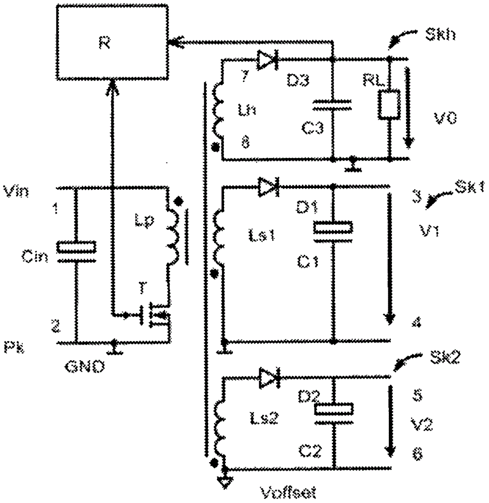
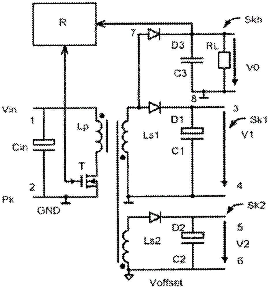
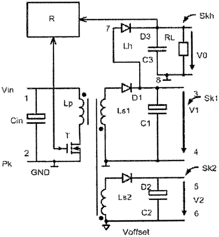
[0020] Figure 1-3 A primary circuit Pk is shown in each case as a common circuit component, in which a series circuit is connected between the two input voltage terminals 1, 2, which is formed from the primary coil Lp and in the example shown as The switching element T of the MOSFET is composed. A series circuit consisting of a primary coil Lp and a switching element T is connected in parallel with an input capacitor Cin for stabilizing the input voltage Vin. The potential at the second terminal 2 for the input voltage Vin is the reference potential GND.

[0021] Two secondary coils Ls1 , Ls2 , which are part of the first secondary circuit Sk1 and the second secondary circuit Sk2 , are magnetically coupled on the secondary side to the primary coil Lp of the primary circuit Pk. The voltage induced in the secondary coils Ls1, Ls2 is applied to the output capacitor C1 or C2 via the diode D1 or D2, respectively, thereby charging it. At the output capacitors C1 , C2 the output ...


PUM


Abstract

A switching controller for the generation of a plurality of DC voltages includes an auxiliary secondary circuit (Skh) in addition to a primary circuit (Pk) and at least two main secondary circuits (Sk1, Sk2). Only the auxiliary secondary circuit (Skh) is controlled by a control circuit (R). The auxiliary secondary circuit (Skh) operates in a virtually powerless manner, wherein the time constant of a parallel circuit has a third output capacitor (C3) and an auxiliary load resistor (RL) is smaller than the average time constants of at least the first and second main secondary circuits (Ls1, Ls2), which are defined by the output capacitors (C1, C2) thereof and the average rating values of the load resistors to be connected.

Description

technical field [0001] This specification relates to a switching regulator for generating a plurality of direct voltages, the switching regulator having first and second input voltage terminals, between which a primary circuit is connected, the primary circuit being connected by at least one A series arrangement consisting of a primary coil and a first controllable switching device, the switching regulator having at least a first pair and a second pair of output voltage terminals, said output voltage terminals having a first or a second output for high A terminal for a voltage potential and a first or a second terminal for a low output voltage potential. Background technique [0002] Furthermore, the switching regulator has at least one first and second secondary circuit, which is formed as a first or a second secondary coil, each magnetically coupled to the primary coil, wherein each first coil of the secondary coil terminal is connected to the first or the second terminal...

Claims


Application Information

Patent Timeline
Patent Type & Authority Applications(China)
IPC IPC(8): H02M3/335
CPCH02M3/33561H02M3/33507H02M1/0025
Inventor C·哈根米勒T·弗兰茨W·施罗德
Owner VTESCO TECH GMBH
Why Eureka
Try Eureka