Microwave signal coupling apparatus

A coupling device and microwave signal technology, applied in the microwave field, can solve problems such as single function, poor product quality stability, and complicated microwave solid-state component testing methods, and achieve the effects of advanced functions, reliable quality and simple structure.

Active Publication Date: 2017-02-15
CHINA ELECTRONIC TECH GRP CORP NO 38 RES INST
View PDF5 Cites 4 Cited by
  • Summary
  • Abstract
  • Description
  • Claims
  • Application Information

AI Technical Summary

Problems solved by technology

[0004] The technical problem to be solved by the present invention lies in the problems of traditional microwave solid-state component testing methods such as complex testing methods, single function, and poor product quality stability. Therefore, a microwave signal coupling device is provided here

Method used


Image

  • Microwave signal coupling apparatus
  • Microwave signal coupling apparatus
  • Microwave signal coupling apparatus

Examples


Embodiment Construction

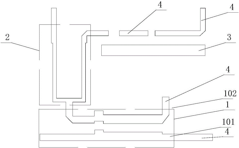
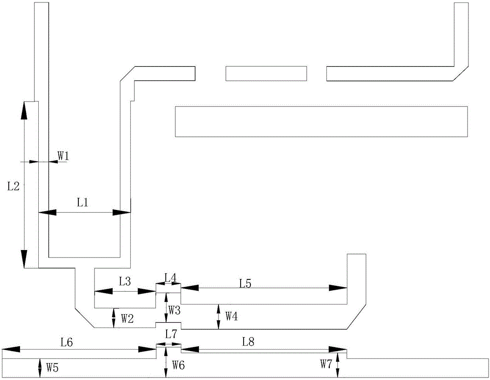
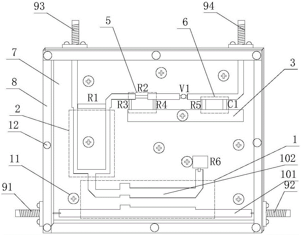
[0034] Such as Figure 1-3 As shown, a microwave signal coupling device includes a microstrip plate 7, a transmission microstrip 4, a coupler 1, a distributor 2, a π attenuator 5, a detector V1, a filter circuit 6, a grounding microstrip 3, and a resistor R6. Transmission microstrip 4 , coupler 1 , distributor 2 , π attenuator 5 , detector V1 , filter circuit 6 , grounding microstrip 3 , and resistor R6 are all arranged on microstrip board 7 .

[0035] The distributor 2 includes a first output terminal and a second output terminal of the distributor, and an isolation resistor R1 is arranged between the first output terminal and the second output terminal of the distributor. Distributor 2 can include multiple output ports, so that multiple coupled signals can be output. Optimally, in this solution, distributor 2 is a 1:2 distributor, which has a simple structure and can realize coupled signals, continuous or pulse The voltage signal is output as two channels respectively. The...


PUM


Abstract

A microwave signal coupling apparatus comprises a micro-strip plate, a transmission microstrip, a coupler, a distributor, a pi attenuator, a detector V1, a filter circuit, a grounding microstrip and a resistor R6. An isolation resistor R1 is arranged between a first output terminal and a second output terminal of the distributor. The coupler comprises an input terminal and three output terminals. The three output terminals are a first output terminal of the coupler, a second output terminal of the coupler and a third output terminal of the coupler. A first input terminal of the coupler is taken as an input terminal of the whole apparatus. The second output terminal of the coupler is taken as a first output terminal of the whole apparatus. The second output terminal of the coupler is connected to an input terminal of the distributor. The first output terminal of the distributor is taken as a second output terminal of the apparatus. The second output terminal of the distributor, an input terminal of the pi attenuator, an output terminal of the pi attenuator, the detector V1 and an input terminal of the filter circuit are successively connected in series through the transmission microstrip. The apparatus has advantages of advanced functions, reliable quality, convenient usage and a wide suitable range.

Description

technical field [0001] The invention relates to the microwave field, in particular to a microwave signal coupling device. Background technique [0002] With the development and progress of microwave technology, microwave solid-state components have been widely used in radar, communication, meteorology, safety detection and other industries, bringing more safety and convenience to our daily life. With the development and progress of society, various industries have also put forward higher requirements for the advanced functions and quality stability of various microwave solid-state components to cope with the ever-changing social development. [0003] At present, all kinds of microwave solid-state components have problems such as complex testing methods, single functions, and poor product quality stability. These practical problems have prompted microwave devices to be updated in the direction of advanced functions and stable quality. Microwave signal coupler is an importan...

Claims


Application Information

Patent Timeline
Patent Type & Authority Applications(China)
IPC IPC(8): H04B3/56
CPCH04B3/56H04B2203/5487
Inventor 李正江桑飞潘华府王华元叶宝江徐静
Owner CHINA ELECTRONIC TECH GRP CORP NO 38 RES INST
Why Eureka
Try Eureka