Cloud-tilt upgrade method of cloud-tilt control system and cloud-tilt control system

A control system and PTZ technology, applied in transmission systems, digital transmission systems, data exchange networks, etc., can solve the problems of inability to control the center to send signals, long distances, and high labor costs in the PTZ upgrade process, saving labor costs. and time cost effects

Active Publication Date: 2020-04-21
SHENZHEN INFINOVA
View PDF4 Cites 0 Cited by
  • Summary
  • Abstract
  • Description
  • Claims
  • Application Information

AI Technical Summary

Problems solved by technology

In the existing pan-tilt control system, due to the long distance between the control center and the pan-tilt, there is a certain time delay in the process of sending the signal sent by the control center to the pan-tilt through a pair of optical transceivers; and, the signal can only be transmitted by The control center sends to the PTZ through a pair of optical transceivers, but the PTZ cannot send signals to the control center through a pair of optical transceivers, so that the control center cannot determine whether the PTZ can receive the signal sent by the control center
During the PTZ upgrade process of the PTZ control system, the control center uses XMODEM to send the upgrade data to the PTZ. Since the signal can only be transmitted in one direction and there is a time delay in the transmission process, the control center cannot determine whether the PTZ can receive the update data. In order to complete the PTZ upgrade after verifying the correct upgrade data, maintenance personnel need to arrive at the site for maintenance and upgrade, which makes the PTZ upgrade process of the PTZ control system expensive.

Method used


Image

  • Cloud-tilt upgrade method of cloud-tilt control system and cloud-tilt control system
  • Cloud-tilt upgrade method of cloud-tilt control system and cloud-tilt control system

Examples


Embodiment 1

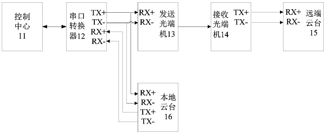
[0029] figure 1 A schematic frame diagram of the pan-tilt control system in this embodiment is shown. Such as figure 1 As shown, the PTZ control system includes a control center 11, a serial port converter 12 connected to the control center 11, a transmitting optical terminal 13 connected to the serial converter 12 and a local PTZ 16, and a receiving optical terminal connected to the transmitting optical terminal 13 through an optical fiber 14, and the remote cloud platform 15 that links to each other with receiving optical terminal 14. Specifically, the serial port converter 12 is 232 to 422 serial port converters, and the control center 11 is connected with the 232 to 422 serial port converters through the 232 serial port lines; connected; the receiving optical transceiver 14 is connected with the remote cloud platform 15 through a 485 serial port line. Wherein, the local pan / tilt 16 can communicate bidirectionally with the control center 11 through the serial port conver...

Embodiment 2

[0043] figure 1 A schematic frame diagram of the pan-tilt control system in this embodiment is shown. Such as figure 1 As shown, the PTZ control system includes a control center 11, a serial port converter 12 connected to the control center 11, a transmitting optical terminal 13 connected to the serial converter 12 and a local PTZ 16, and a receiving optical terminal connected to the transmitting optical terminal 13 through an optical fiber 14, and the remote cloud platform 15 that links to each other with receiving optical terminal 14. Specifically, the serial port converter 12 is 232 to 422 serial port converters, and the control center 11 is connected with the 232 to 422 serial port converters through the 232 serial port lines; connected; the receiving optical transceiver 14 is connected with the remote cloud platform 15 through a 485 serial port line. Wherein, the local pan / tilt 16 can communicate bidirectionally with the control center 11 through the serial port conver...


PUM


Abstract

The invention discloses a pan-tilt upgrading method and device of a pan-tilt control system. The pan-tilt control system comprises a control center, a serial port converter, a transmission optical transceiver, a local pan-tilt, a reception optical transceiver and a remote pan-tilt; the control center sends a current frame of upgrading data to the transmission optical transceiver and the local pan-tilt; the transmission optical transceiver sends the current frame of upgrading data to the remote pan-tilt; the local pan-tilt checks the received current frame of upgrading data to generate a positive response signal or a negative response signal, and sends the positive response signal or the negative response signal to the control center; the control center sends next frame of upgrading data to serve as the current frame of upgrading data when receiving the positive response signal, and repeatedly sends the current frame of upgrading data when receiving the negative response signal; and the remote pan-tilt receives the current frame of upgrading data and upgrades the remote pan-tilt based on all current frames of upgrading data. By adoption of the pan-tilt upgrading method and device of the pan-tilt control system, the remote pan-tilt is upgraded under the assistance of the local pan-tilt, and intelligent upgrade of the remote pan-tilt is realized.

Description

technical field [0001] The invention relates to the field of platform upgrading, in particular to a platform upgrading method of a platform control system and a platform control system. Background technique [0002] Currently, the PTZs installed on the market do not have network functions. In the existing PTZ control system, the PTZs are connected to the control center through a pair of optical transceivers, and the PTZs are set far away from the control center. In the existing pan-tilt control system, due to the long distance between the control center and the pan-tilt, there is a certain time delay in the process of sending the signal sent by the control center to the pan-tilt through a pair of optical transceivers; and, the signal can only be transmitted by The control center sends to the PTZ through a pair of optical transceivers, but the PTZ cannot send signals to the control center through a pair of optical transceivers, so that the control center cannot determine whet...

Claims


Application Information

Patent Timeline
Patent Type & Authority Patents(China)
IPC IPC(8): H04L12/24H04L29/08
CPCH04L41/0246H04L41/082H04L67/10
Inventor 熊海波刘志军
Owner SHENZHEN INFINOVA
Why Eureka
Try Eureka