Telescopic boom system of ultrahigh aerial ladder fire truck lifting stage by stage

A technology of a ladder fire truck and telescopic boom, which is applied in the direction of lifting device, fire rescue, etc., can solve the problems of untimely firefighting, which will bring serious consequences, limited capacity of fire hydrants, and difficulty in firefighting and rescue.

Inactive Publication Date: 2017-02-22
王明中
View PDF4 Cites 15 Cited by
  • Summary
  • Abstract
  • Description
  • Claims
  • Application Information

AI Technical Summary

Problems solved by technology

[0003] Nowadays, fire trucks have become a must for fire protection in every city, and with the sky development of big cities, various high-rise buildings are coming as scheduled, and the resulting fire protection problems on high floors are more prominent. The telescopic arm adopts the internal oil cylinder to connect the pulley, and the number and height of the telescopic arms are greatly limited. Taking the existing tallest fire ladder truck as an example, the whole vehicle is 16.7 meters long and the maximum height is only 101 meters (can be rise to 35 floors), and once a fire breaks out in a high-rise over 35 floors, it can only be extinguished by the fire hydrant of the building itself. Untimely extinguishing will bring serious consequences. At the same time, relying on firefighters to enter the high-rise fire from the bottom will also increase various potential dangers. This will undoubtedly cause many difficulties for high-level fire fighting and rescue.

Method used


Image

  • Telescopic boom system of ultrahigh aerial ladder fire truck lifting stage by stage
  • Telescopic boom system of ultrahigh aerial ladder fire truck lifting stage by stage
  • Telescopic boom system of ultrahigh aerial ladder fire truck lifting stage by stage

Examples


Embodiment Construction

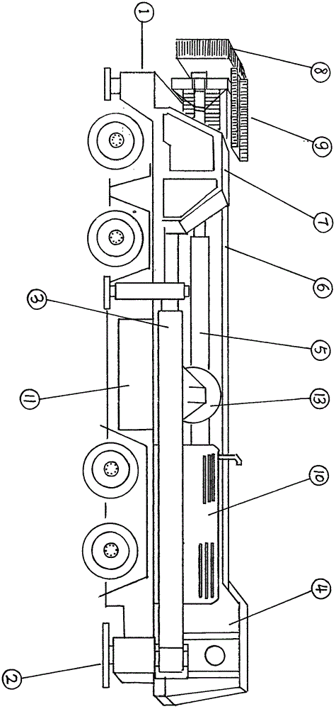
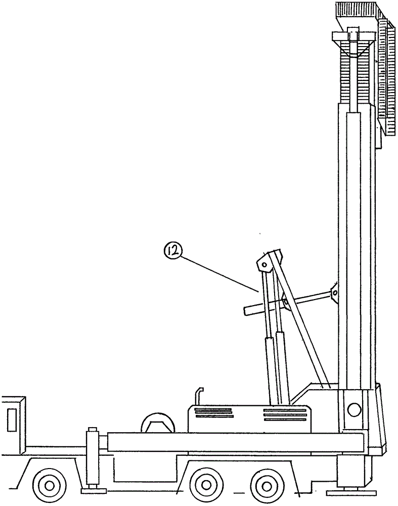
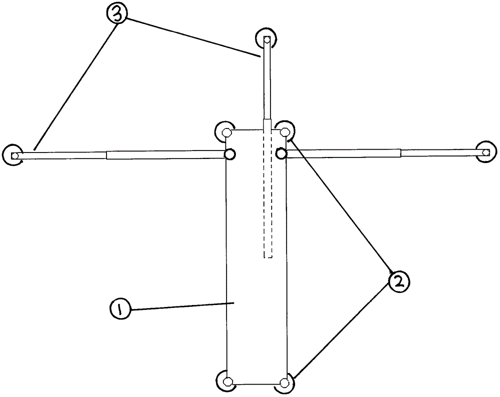
[0027] according to figure 1 , figure 2 , image 3 It can be seen that the fire truck consists of a car body (1), a base main support (2), a base auxiliary support (3), a base (4), an ultra-long stroke multi-stage oil cylinder (5), a free telescopic arm (6), A two-way cab (7), an operating platform (8), an electric telescopic ladder (9), a power system (10), and a hydraulic oil tank (11) etc., and the base main support (2) is installed on both sides and The lower part of the cab at the front end of the vehicle is directly pushed to the ground by the oil cylinder to form the main force supporting the vehicle body. The sub-support (3) of the base is installed on the base (4), and is supported by the rotating support arms on both sides and the telescopic support at the rear. The rotating support arms on both sides are close to the car body when contracted, and are swung out to both sides by the motor rotation mode when in use. The telescopic length can be freely controlled acc...


PUM


Abstract

The invention relates to the field of fire-fighting machinery, and particularly relates to a telescopic boom of an aerial ladder fire truck. The telescopic boom of a telescopic boom system of an ultrahigh aerial ladder fire truck lifting stage by stage can be drawn out as an antenna; two groups of multi-stage oil cylinders with ultralong strokes are arranged at the two ends of the telescopic boom; an electric movable pin pushing device is arranged at the top end of each oil cylinder; the telescopic boom is pushed out upwards by the multi-stage oil cylinders with the ultralong strokes and stops at a corresponding position under the stroke limiting action of an induction switch during working of equipment; the second stage of the telescopic boom and one section of ascending telescopic boom are located through location pins; and at this moment, the two sections of the telescopic boom are connected into one piece; a movable pin is retreated by the electric movable pin pushing device; the multi-stage oil cylinders with the ultralong strokes are descended to the position of the second stage of the telescopic boom; and the telescopic boom can be sequentially pushed out through repeating the abovementioned action. More telescopic booms can be accommodated in the main telescopic boom in a stress range of the strength of the telescopic boom because the telescopic boom uses an external thrust device, and therefore, a high lifting height can be achieved.

Description

[0001] Technical field [0002] The invention relates to the field of fire-fighting machinery, in particular to a telescopic arm of a fire-fighting aerial ladder vehicle. Background technique [0003] Nowadays, fire trucks have become a must for fire protection in every city, and with the sky development of big cities, various high-rise buildings are coming as scheduled, and the resulting fire protection problems on high floors are more prominent. The telescopic arm adopts the internal oil cylinder to connect the pulley, and the number and height of the telescopic arms are greatly limited. Taking the existing tallest fire ladder truck as an example, the whole vehicle is 16.7 meters long and the maximum height is only 101 meters (can be rise to 35 floors), and once a fire breaks out in a high-rise over 35 floors, it can only be extinguished by the fire hydrant of the building itself. Untimely extinguishing will bring serious consequences, and relying on firefighters to enter h...

Claims


Application Information

Patent Timeline
Patent Type & Authority Applications(China)
IPC IPC(8): A62C27/00B66F11/04A62C31/28
CPCA62C27/00A62C31/28B66F11/04
Inventor 王明中
Owner 王明中
Why Eureka
Try Eureka