Bar image detection mechanism

An image detection and bar technology, which is applied in the field of mechanisms for online image detection of bars, can solve the problems of inability to grasp and rotate, the bar cannot be released, and the positioning groove is set too deep.

Active Publication Date: 2017-02-22
北京凯视佳光电设备有限公司
View PDF7 Cites 2 Cited by
  • Summary
  • Abstract
  • Description
  • Claims
  • Application Information

AI Technical Summary

Problems solved by technology

[0005] The above method cannot set the positioning groove too deep, otherwise the bar cannot be released; there must be a negative pressure device, otherwise it cannot be grasped and rotated
To generate negative pressure, a vacuum generating system is necessary, so the detection mechanism must be relatively complicated

Method used


Image

  • Bar image detection mechanism
  • Bar image detection mechanism

Examples


Embodiment Construction

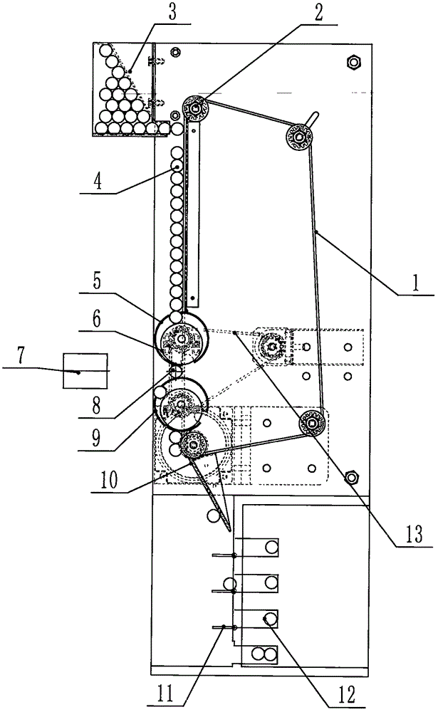
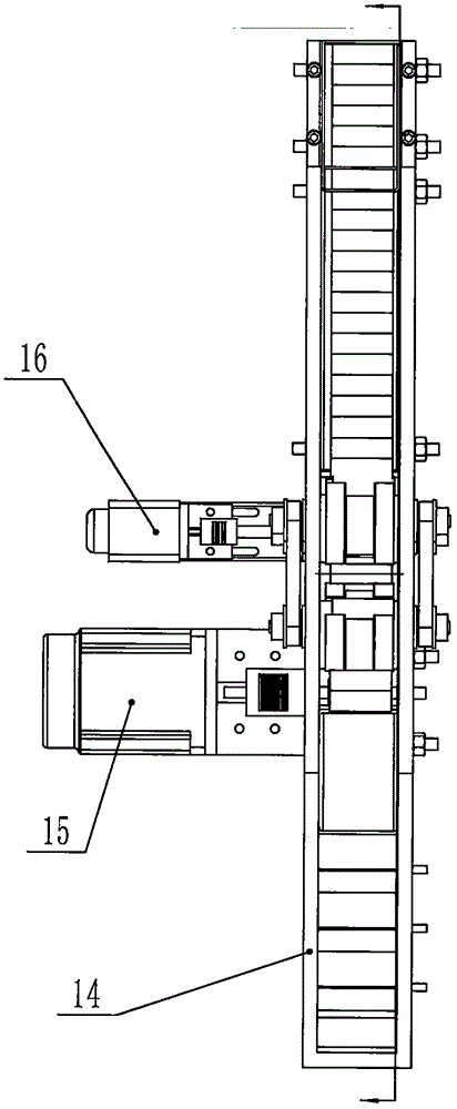
[0016] The implementation and operation process of the present invention are as follows: put the bar to be detected (4) into the storage box (3), start the feeding motor (15), the rotating motor (16), feed the synchronous belt (1) and feed Material transfer wheel (5), discharge material transfer wheel (9) run. The bar (4) reaches the edge of the feed transfer wheel (5) driven by the feed timing belt (1). Parallel card slots, the depth of the card slots can prevent the bar from falling off after the bar is stuck. The transfer wheels (5), (9) are fixed with an eccentric wheel (6) eccentric to it, and the center of the eccentric wheel (6) is biased towards the discharge position, so that the distance between the transfer wheels (5), (9) and the outer circumference of the eccentric wheel (6) is the largest when the feed transfer wheels (5), (9) are feeding, and the transfer wheels (5), (9) The distance from the outer circumference of the eccentric wheel (6) is the smallest to ens...


PUM


Abstract

Disclosed is a bar image detection mechanism. The mechanism is simple in structure and free of a vacuum system. The mechanism comprises a feeding synchronous belt, synchronous wheels, a storage box, bars, a feeding transferring wheel, eccentric wheels, a detection head, a detection position, a discharging transferring wheel, a discharging plate, a dividing plate, a dividing groove, a rotating synchronous belt, a discharging box, a feeding motor and a rotating motor; each transferring wheel is composed of two half wheels, the feeding synchronous belt passes the middles of the transferring wheels, the gap between the two transferring wheels is adjustable, and due to arrangement of the number of clamping grooves in the transferring wheels, the arc line between two clamping grooves can drive the bars to sufficiently rotate on the detection position; due to the depth of the clamping grooves, the bars are clamped and cannot fall off, and the next bars cannot be disturbed; the eccentric wheels are arranged in the transferring wheels, and deviate from the discharging position, and it is ensured that during feeding, the bars are sufficiently clamped in the clamping grooves, and during discharging, the bars are sufficiently separated from the clamping grooves. The dividing plate and the dividing groove are arranged in the discharging box, due to the dividing plate, the bars pass through or enter the dividing groove, and clamping and separation of the bars can be achieved through the eccentric wheels and the transferring wheels.

Description

[0001] (1) Technical field [0002] The patent of the present invention relates to the technical field of image detection and non-contact detection, especially the mechanism for online image detection of rods. [0003] (2) Background technology [0004] The existing general method for detecting bars is to put the bars on a conveyor belt or a transmission wheel, and make them pass through a detection instrument in sequence to detect the appearance of the bars. This method cannot detect the back of the bar. For this reason, the patent application publication number is that the document of CN105021629 A provides a kind of solution. This method includes an infeed drum, an outfeed drum and a detection assembly. The two drums rotate synchronously in the same direction, and are arranged parallel to each other in parallel. There is a gap smaller than the outer diameter of the bar between the two drums, which is the detection position of the bar. The outer sides of the rims of the tw...

Claims


Application Information

Patent Timeline
Patent Type & Authority Applications(China)
IPC IPC(8): B07C5/00B07C5/02B07C5/36
CPCB07C5/00B07C5/02B07C5/362
Inventor 郭坡韩国立
Owner 北京凯视佳光电设备有限公司
Why Eureka
Try Eureka