
Ejection system and operation method thereof

An ejection system and an ejection technology, applied in the field of ejection systems, can solve the problems that the burr 1 of the bump hole cannot be completely repaired, affects the output, and delays time, etc., so as to solve the problem of flashing on the bump surface, improve the pressing condition, Effect of improving mold life

Inactive Publication Date: 2017-02-22
SHANGHAI XPARTNER ROBOTICS
View PDF0 Cites 4 Cited by
  • Summary
  • Abstract
  • Description
  • Claims
  • Application Information

AI Technical Summary

Problems solved by technology

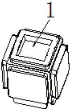
During the mold clamping process, since the insert is still in the state of being pushed out by the spring, it needs to be pressed into position with the parting surface of the master mold. After many times of pressing, the parting surface is not smooth, resulting in flashing of the product (such as figure 1 shown)
The appearance of flash will affect the quality of the product, and the production cannot continue. It needs maintenance and affects the production.
[0003] More specifically, during the mold molding of the regular cube product, the burr 1 in the middle of the collision hole cannot be completely repaired, and it will appear repeatedly
This kind of perforation burr1 leads to regular mold maintenance, which delays time, affects output, and cannot meet the needs of the production line.

Method used


Image

  • Ejection system and operation method thereof
  • Ejection system and operation method thereof
  • Ejection system and operation method thereof

Examples


Embodiment Construction

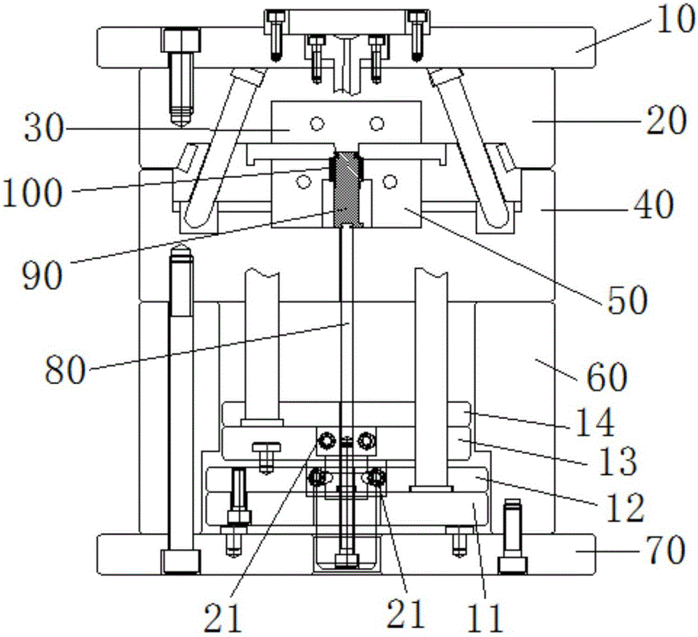
[0020] figure 2 is an overall schematic diagram of the ejection system according to a preferred embodiment of the present invention.

[0021] Such as figure 2 As shown, the ejection system according to a preferred embodiment of the present invention includes: an upper fixed plate 10, a front template 20 fixed below the upper fixed plate 10, a front mold core 30 fixed in the front template 20, a lower fixed plate 70, a fixed The square iron 60 on the lower fixing plate 70, the back template 40 fixed on the square iron 60, and the back mold core 50 fixed in the back template 40.

[0022] Among them, a top stick groove is arranged through the lower fixing plate 70, the square iron 60, the back template 40 and the back mold core 50, and a top stick 80 is arranged in the top stick groove, and a top of the top stick 80 is arranged to prevent the product 100 to be ejected. The insert 90.

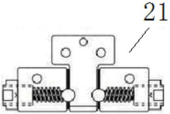
[0023] And wherein, the first ejector plate 11, the second ejector plate 12, the third eje...


PUM


Abstract

The invention discloses an ejection system and an operation method thereof. The ejection system comprises an upper fixing plate, a front die plate fixed below the upper fixing plate, a front die core fixed in the front die plate, a lower fixing plate, square iron fixed to the lower fixing plate, a rear die plate fixed to the square iron and a rear die core fixed in the rear die plate. An ejector groove is formed in the lower fixing plate, the square iron, the rear die plate and the rear die core in a penetrating manner. An ejector is arranged in the ejector groove. An insert used for carrying a to-be-ejected product is arranged at the top end of the ejector. In addition, a first ejection pin device and a second ejection pin device are sequentially arranged in the square iron and around the ejector from bottom to top. The first ejection pin device and the second ejection pin device are connected through a mechanical opening and closing device. In the square iron, the width of the upper end portion is smaller relative to the width of the lower end portion, the width of the first ejection pin device is smaller than the width of the upper end portion of the square iron, and the width of the second ejection pin device is larger than the width of the upper end portion of the square iron and smaller than the width of the lower end portion of the square iron.

Description

technical field [0001] The invention relates to the field of mold design, in particular to an ejection system and an operation method thereof. Background technique [0002] The positive cube mold uses a spring to eject the insert to make the undercut of the product come out smoothly. During the mold clamping process, since the insert is still in the state of being pushed out by the spring, it needs to be pressed into position with the parting surface of the master mold. After many times of pressing, the parting surface is not smooth, resulting in flashing of the product (such as figure 1 shown). The appearance of flash will affect the product quality, make it impossible to continue production, need maintenance, and affect production. [0003] More specifically, during the mold molding of the cube product, the burr 1 in the middle of the collision hole cannot be completely repaired, and it will appear repeatedly. This kind of perforation burr leads to regular maintenance o...

Claims


Application Information

Patent Timeline
Patent Type & Authority Applications(China)
IPC IPC(8): B29C33/44
CPCB29C33/44
Inventor 恽为民孙军庞作伟
Owner SHANGHAI XPARTNER ROBOTICS
Learn More