Flying car

A flying car and body technology, applied in the field of flying cars, can solve problems such as structural fatigue, and achieve the effect of less energy consumption and long range

Inactive Publication Date: 2017-02-22
龙川
View PDF0 Cites 7 Cited by
  • Summary
  • Abstract
  • Description
  • Claims
  • Application Information

AI Technical Summary

Problems solved by technology

[0003] Chinese invention patent 2011100865703 discloses a ducted wing system and an aircraft using the ducted wing system. This ducted wing system can generate lift and thrust at the same time. It is a highly integrated system that promotes aerodynamic integration. Through The tilting of the ducted wing system can enable the aircraft using this ducted wing system to achieve vertical take-off and landing and high-speed flight, but part of the fan of this ducted wing system is in the ducted wing, and a part is in the ducted wing. Outside the wing, there will be periodic vibration during work, which is easy to make the structure fatigue; Chinese invention patent 2014101730228 discloses a ducted wing system and an aircraft using this system, and has made further improvements to the above patents, making this The ducted wing system and the aircraft using this system are more perfect, but this ducted wing system has not yet been used in the field of flying cars
[0004] The existing ducted fan system is also a system that promotes aerodynamic integration. Through proper settings, the ducted fan system can make the corresponding aircraft take off and land vertically. After tilting forward, the fan can push the aircraft forward, and the duct can generate lift. , but the ducted fan system has not been applied to flying cars in this way

Method used


Image

  • Flying car
  • Flying car
  • Flying car

Examples


Embodiment 1

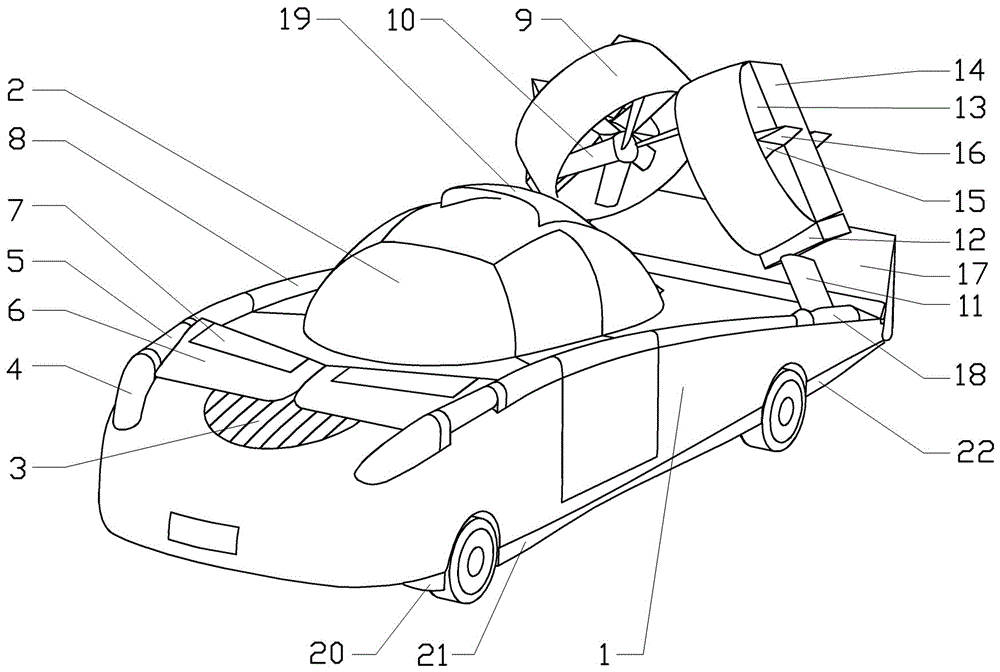
[0022] Example one: such as figure 1 , 2 , 3 and 4, the integrated propulsion pneumatic system is a ducted fan system. The ducted fan system includes duct 9, fan 10, horizontal support stabilizer 13, horizontally supports flaperon 14 at the rear edge of stabilizer 13, vertical The stabilizer 15 is supported, and the rudder 16 at the rear edge of the stabilizer 15 is supported vertically.

[0023] This embodiment is a conventional ducted fan system. The duct 9 has a symmetrical airfoil profile. The fan 10 is a coaxial fan. The horizontal support stabilizer 13 and the vertical support stabilizer 15 cross to support the motor driving the fan 10. When the duct fan is in a horizontal attitude, it can generate direct lift to make the flying car take off vertically. When the duct fan system is in a vertical attitude with a small angle of attack, the airfoil composed of stabilizer 13 and flaperon 14 and duct 9 can be supported horizontally. The lift is generated, and the fan 10 can gener...

Embodiment 2

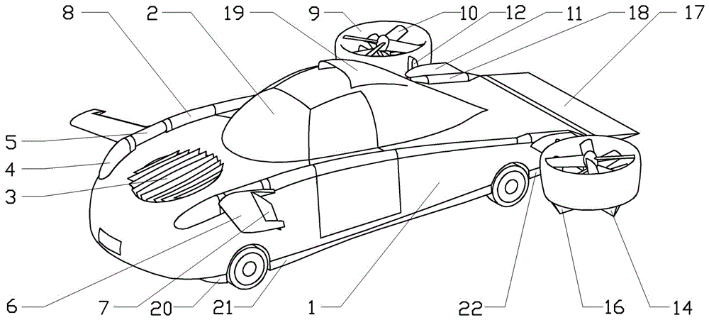
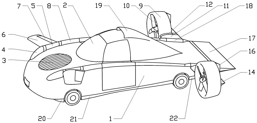
[0025] Embodiment two: such as Figure 5 , 6 , 7 and 8, the integrated propulsion aerodynamic system is a ducted wing system. The ducted wing system includes ducted wing 23, fan 10, flaperon 24 at the upper rear edge of ducted wing, support wing, and support wing The middle flap 28 at the trailing edge, the lower flap 27 at the lower rear edge of the ducted wing, the upper rudder 25 at the upper rear edge of the ducted wing 23, the lower rudder 26 at the lower rear edge of the ducted wing 23, at the fan At the back of 10, on the upper part of the duct wing 23, there is a slit through the duct wing 23.

[0026] The upper part, lower part, and support wing of the ducted wing 23 in this embodiment are all asymmetrical airfoils, and the fan 10 is a coaxial fan, and the slipstream generated has no slipstream torsion, which can provide good support for the support wing and ducted wing. The upper and lower parts of 23 are boosted by power, and the slipstream of the fan 10 can also pass ...


PUM


Abstract

A flying car comprises a car body in the shape of a lifting body and a water-drop-shaped driving cabin positioned in the middle of the car body. A lifting fan is arranged on the front portion of the car body, an air inlet of the lifting fan is provided with shutters in vertical arrangement, an air outlet is provided with shutters in transverse arrangement, plump car lamps are arranged on two sides of the head of the car body, the rear portion of each car lamp naturally extends to be provided with a duck wing rotating shaft, a wing root of a duck wing composed of a duck wing stabilizing plane and a control plane is connected onto each duck wing rotating shaft, and a propelling pneumatic integrated system is arranged on each of two sides of the rear portion of the car body and can be folded and unfolded through a foldable wing section. Through forward-backward inclination rotating of the propelling pneumatic integrated system and combining with the lifting fan, the duck wings and the car body in the shape of the lifting body, the flying car can vertically take off and land, can fly at high speed and is wide in flying range and low in energy consumption.

Description

Technical field [0001] The invention relates to the field of land and air amphibious vehicles, in particular to a flying car. Background technique [0002] Chinese invention patent 2016101724705 discloses a flying car. This flying car is equipped with a lift fan at the front and two foldable ducted fans at the rear. When the ducted fan is folded, the flying car has a smaller width and can When driving on the road, when the ducted fan is turned on, the flying car becomes an aircraft with a three-fan layout. The three fans enable the flying car to achieve vertical take-off and landing. However, this flying car has no wings and can only use the fan to generate direct lift to maintain the flying car. Flight has limited speed and range, and consumes a lot of energy. [0003] Chinese invention patent 2011100865703 discloses a ducted wing system and an aircraft using ducted wing system. This ducted wing system can generate lift and thrust at the same time. It is a highly integrated and p...

Claims


Application Information

Patent Timeline
Patent Type & Authority Applications(China)
IPC IPC(8): B60F5/00
CPCB60F5/006
Inventor 龙川
Owner 龙川
Why Eureka
Try Eureka