
Multifunctional brake release indicator and control system thereof

A brake relief and indicator technology, applied in brake safety systems, brakes, pneumatic brakes, etc., can solve problems such as inaccurate display, misjudgment by maintenance personnel, safety accidents, etc., to achieve accurate display help, reduce maintenance time, The effect of avoiding safety accidents

Active Publication Date: 2017-02-22
CRRC CHANGCHUN RAILWAY VEHICLES CO LTD
View PDF8 Cites 4 Cited by
  • Summary
  • Abstract
  • Description
  • Claims
  • Application Information

AI Technical Summary

Problems solved by technology

However, the current brake relief display device for rail vehicles can only display the braking status of the air brake, and after the train has been parked for a long time, the compressed air in the vehicle braking system has leaked and emptied, and it will not be able to correctly display the train status.
At the same time, for rail vehicles with mechanical brakes (hand brake devices) installed, the release status of mechanical brakes cannot be displayed
These inaccurate displays bring troubles to testers, and may lead to misjudgments by maintenance personnel, resulting in security incidents

Method used


Image

  • Multifunctional brake release indicator and control system thereof
  • Multifunctional brake release indicator and control system thereof
  • Multifunctional brake release indicator and control system thereof

Examples


Embodiment Construction

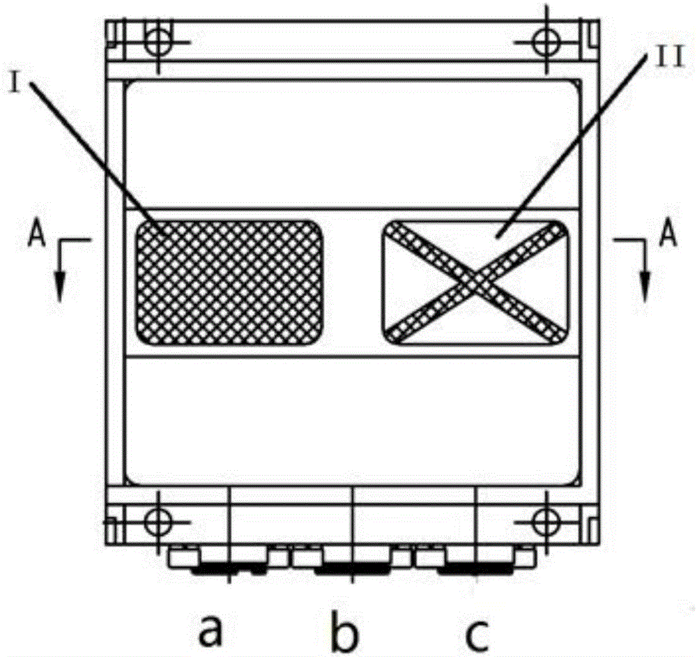
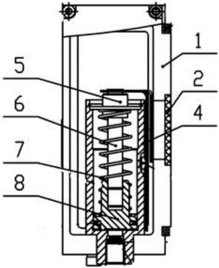
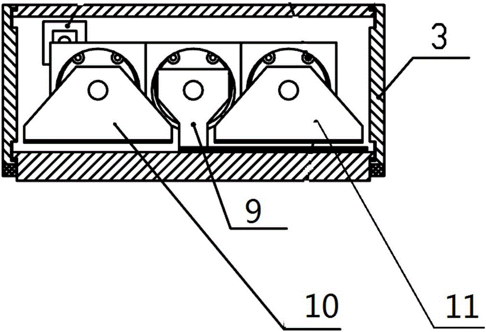
[0014] refer to figure 1 , figure 2 , image 3 , the multifunctional brake relief indicator of the present invention is composed of a housing 1, a window 2, a cover 3, a cylinder block 4, a cylinder head 5, a piston rod 6, a return spring 7, a piston 8, a total wind pressure display panel 9, a brake The status display panel 10 and the hand brake\brake status display panel 11 are composed. The shell 1 and the cover 3 form the shell frame of the indicator. The function of the window 2 is the display window of the braking state. Cylinder block 4, cylinder head 5, piston rod 6, return spring 7, piston 8 form a piston cylinder and form. There are three piston cylinders in the indicator, which are respectively connected to the air circuit interfaces a, b, and c. Compressed air from a, b, c enters the piston cylinder to push the piston upward. The total air state display board 9, the braking state display board 10, and the hand brake / braking state display board 11 are respecti...


PUM


Abstract

The invention relates to a multifunctional brake release indicator. The multifunctional brake release indicator comprises a shell and a total air pressure display panel, a brake state display panel and a manual brake / brake state display panel which are located in the shell. Two visual windows are formed in the middle of the shell. Each piston cylinder comprises a cylinder body, a cylinder head, a piston rod, a return spring and a piston. Three piston cylinders are arranged in the shell. The total air pressure display panel, the brake state display plane and the manual brake / brake state display panel are respectively connected with the cylinder heads of the three piston cylinders. The bottom surface of each of the three piston cylinders is provided with an interface, and the interfaces are respectively connected with a brake cylinder pipeline, a brake system air source and the output port of a pipeline two-way valve. The whole area of each of the brake state display panel and the manual brake / brake state display panel is divided into an upper part and a lower part, and the upper part and the lower part are painted with different colors. The total air pressure display panel only has half area of each of the brake state display panel and the manual brake / brake state display panel and is painted with a symbol. The multifunctional brake release indicator has the advantages that the states of air braking and mechanical braking are displayed at the same time by using a control system formed by a one-way valve, an air storage cylinder, a stroke valve and a two-way valve to control the indicator, and the state of a brake system can be displayed accurately after a vehicle is parked for a long time and the compressed air of the brake system are leaked and emptied.

Description

technical field [0001] The invention belongs to the field of railway transportation, and in particular relates to a braking state display device and control method for rail vehicles. Background technique [0002] Rail vehicles equipped with disc brake devices are generally equipped with a brake status display device, which is convenient for testers and maintenance personnel to check the brake status of the train very conveniently. However, the current brake mitigation display device for rail vehicles can only display the braking state of the air brake, and after the train is parked for a long time, the compressed air in the vehicle braking system leaks and is emptied, and the train state cannot be displayed correctly. At the same time, for rail vehicles equipped with mechanical brakes (hand brake devices), the release status of mechanical brakes cannot be displayed. These inaccurate displays bring troubles to testers, and may lead to misjudgments by maintenance personnel, r...

Claims


Application Information

Patent Timeline
IPC IPC(8): B61H11/06B60T17/22
CPCB60T17/228B61H11/06
Inventor 孟繁辉
Owner CRRC CHANGCHUN RAILWAY VEHICLES CO LTD
Learn More