
Automobile and automobile cab fastening structure

A technology for fastening structure and cab, which is applied to the superstructure, superstructure, vehicle components, etc. of trucks, and can solve the problems of insufficient rigidity, strength, relative displacement between cab and chassis, and easily damaged connecting structure, etc. Quick and easy assembly and disassembly

Inactive Publication Date: 2017-02-22
YUNNAN LIFAN JUNMA AUTOMOBILE
View PDF6 Cites 0 Cited by
  • Summary
  • Abstract
  • Description
  • Claims
  • Application Information

AI Technical Summary

Problems solved by technology

[0004] The purpose of the present invention is to provide a fastening structure for the cab of an automobile to solve the problem of insufficient rigidity and strength of the fastening structure of the cab in the prior art, insufficient reliability of the connection between the cab and the chassis, and the fact that the cab will fall under the action of inertia when the car shifts speed. The force applied to the connecting structure between the cab and the chassis is easy to damage the connecting structure, resulting in the relative displacement of the cab and the chassis or the overturning of the cab

Method used


Image

  • Automobile and automobile cab fastening structure
  • Automobile and automobile cab fastening structure
  • Automobile and automobile cab fastening structure

Examples


Embodiment 1

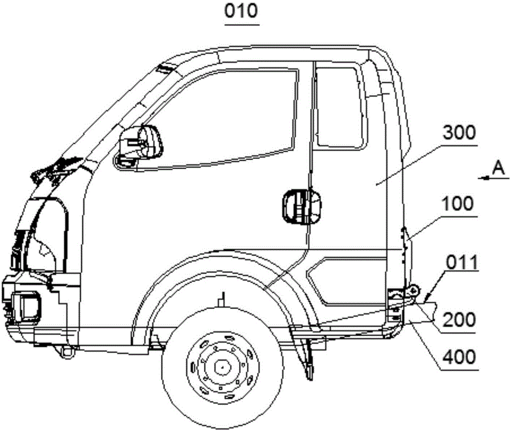
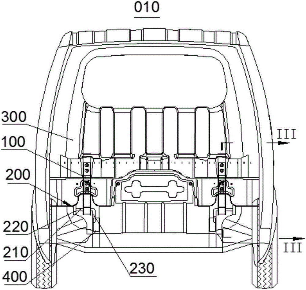
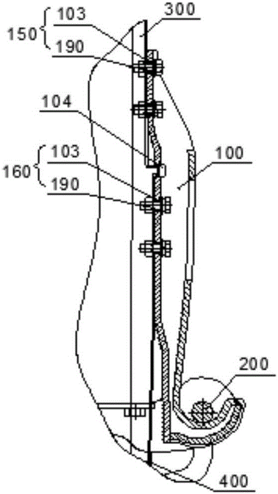
[0051] figure 1 It is a structural schematic diagram of the automobile cab fastening structure 010 in this embodiment; figure 2 Yesfigure 1 A-direction view; image 3 Yes figure 2 Sectional view along line III-III. Please refer to figure 1 (for coordination see figure 2 , image 3 ), the present embodiment provides an automobile cab fastening structure 010, which includes a cab 300, a chassis 400 and a fastening hook 100 with a U-shaped hook portion 140 for connecting the cab 300 and the chassis 400. The chassis 400 is connected with a fixed structure 200, and the two ends of the fixed structure 200 are respectively fixedly connected to the connection surface 011 of the chassis 400 of the automobile 001. There is a matching cross bar 210 spaced from the connection surface 011 between the two ends of the fixed structure 200. The space between the coordinating cross bar 210 and the connecting surface 011 facilitates the fastening and fitting of the hook 100. The coopera...

Embodiment 2

[0065] Image 6 It is a structural schematic diagram of the automobile 001 in the embodiment of the present invention. The automobile 001 of this embodiment has the automobile cab fastening structure 010 in the first embodiment. The rear end of the cab 300 of the automobile 001 is connected to the chassis 400 of the automobile 001 by the fastening structure 010 of the automobile cab in the first embodiment, and the front end can be detachably connected to the chassis 400 of the automobile 001.

[0066] During the start or running of the car 001 in this embodiment, relative acceleration may occur between the cab 300 and the chassis 400 due to inertia. For example, when the car 001 stops suddenly, the driver's cab 300 continues to move forward due to inertia, and the connection between the driver's cab 300 and the chassis 400 will be subjected to a shearing force, and may also generate a moment that causes the driver's cab 300 to overturn forward. The rear end of the cab 300 o...


PUM


Abstract

The invention relates to the field of automobile structures and aims at solving the problem that an existing automobile cab fastening structure is low in strength, troublesome to mount and dismount and operate and a cab cannot be safely locked on a chassis and providing an automobile cab fastening structure. The automobile cab fastening structure comprises a cab, a chassis and a fastening hook for connecting the cab and the chassis, wherein the chassis is connected with a fixing structure. The fastening hook is provided with a first end and a second end detachably connected to the rear surface of the automobile cab. Two ends of the fixing structure are respectively and fixedly connected to the connecting face of the automobile chassis, and a matched cross rod mutually spaced from the connecting face is arranged between the two ends and is matched with the inner side of a U-shaped bent hook portion to limit displacement of the U-shaped bent hook portion with respect to the matched cross rod in the opening direction of the U-shaped bent hook portion and the front-back direction of the U-shaped bent hook portion along the chassis. The invention further provided with the automobile provided with the automobile cab fastening structure. The automobile cab fastening structure has the advantages that the automobile cab fastening structure is high in strength and convenient to mount and dismount, a cab can be well fastened and connected to the chassis, and the automobile is good in safety performance.

Description

technical field [0001] The invention relates to the technical field of automobile structures, in particular to an automobile cab fastening structure. The invention also relates to an automobile equipped with the fastening structure of the automobile cab. Background technique [0002] The fastening structure of the automobile cab refers to the interconnection structure between the cab and the chassis. [0003] The existing cab fastening structure has insufficient rigidity and strength, and the reliability of the connection between the cab and the chassis is not enough. When the car shifts, the force exerted by the cab on the connection structure between the cab and the chassis under the action of inertia is easy to damage the connection structure. Cause the relative displacement between the cab and the chassis or the overturning of the cab. Contents of the invention [0004] The purpose of the present invention is to provide a fastening structure for the cab of an automob...

Claims


Application Information

Patent Timeline
IPC IPC(8): B62D33/077
CPCB62D33/077
Inventor 马李斌龙云朗杨前
Owner YUNNAN LIFAN JUNMA AUTOMOBILE
Features
  • Generate Ideas
  • Intellectual Property
  • Life Sciences
  • Materials
  • Tech Scout
  • Unparalleled Data Quality
  • Higher Quality Content
  • 60% Fewer Hallucinations
Learn More