
a heat shrinking machine

A technology of heat shrinking machine and shrinking space, which is applied in the directions of wrapping paper shrinkage, packaging, wrapping paper, etc., can solve the problems of poor effect, poor heat shrinkage effect, and inability to realize heat shrinkage of packaging, so as to reduce the work and improve the Air flow, the effect of reducing power consumption

Active Publication Date: 2019-12-03
ZHEJIANG DINGYE MACHINERY
View PDF8 Cites 0 Cited by
  • Summary
  • Abstract
  • Description
  • Claims
  • Application Information

AI Technical Summary

Problems solved by technology

[0004] In the heat shrinking machine in the prior art, since the entire frame is directly spliced ​​by a piece of board, it will cause heat to accumulate at the corner during the working process of the heat shrinking machine, and the fan will only Using an ordinary fan can exchange the upper and lower airflow, but the effect of pushing the airflow horizontally is not good, resulting in poor final heat shrinkage effect, and it is impossible to achieve comprehensive heat shrinkage of the package.

Method used


Image

  • a heat shrinking machine
  • a heat shrinking machine
  • a heat shrinking machine

Examples


Embodiment approach

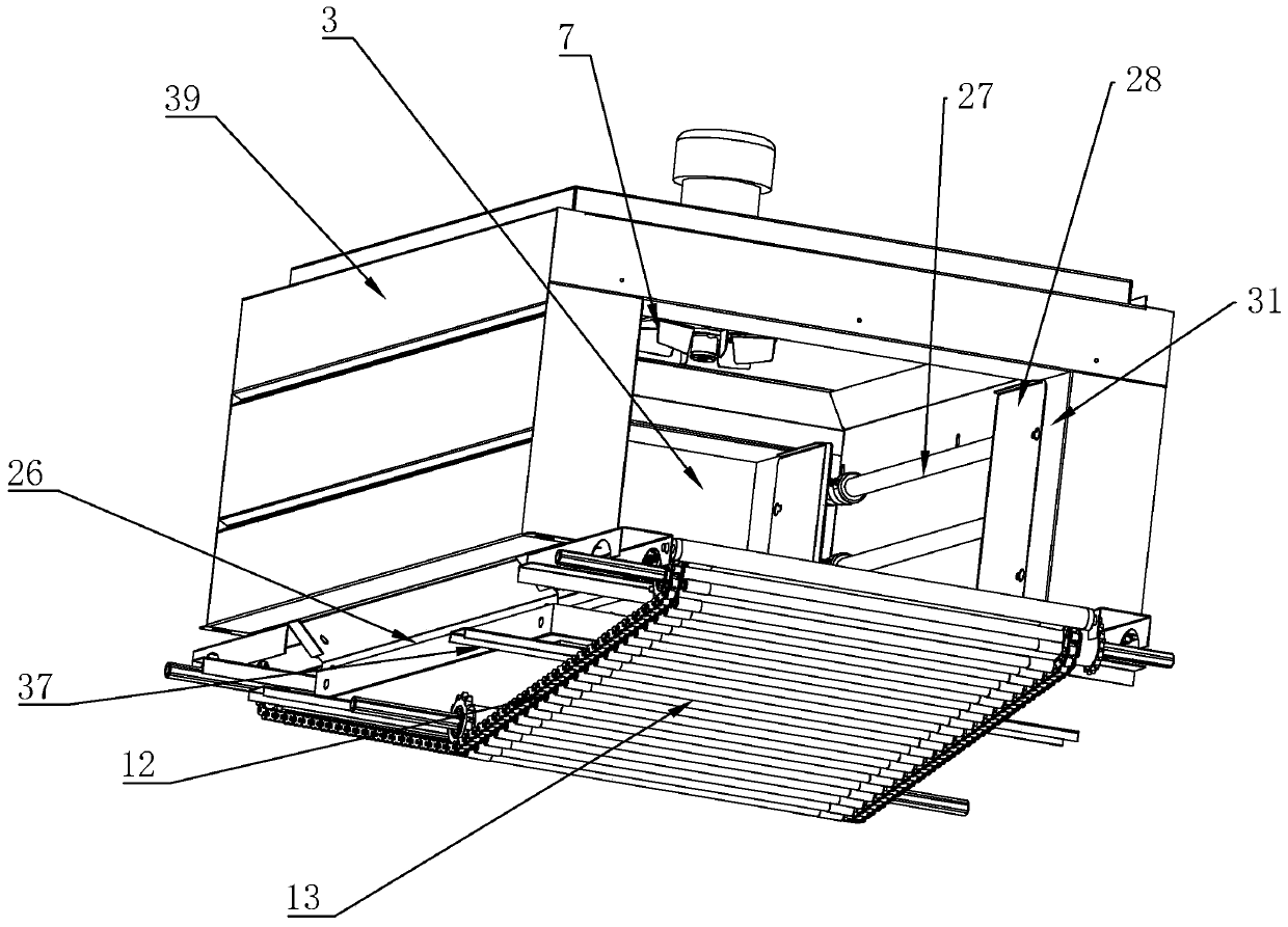
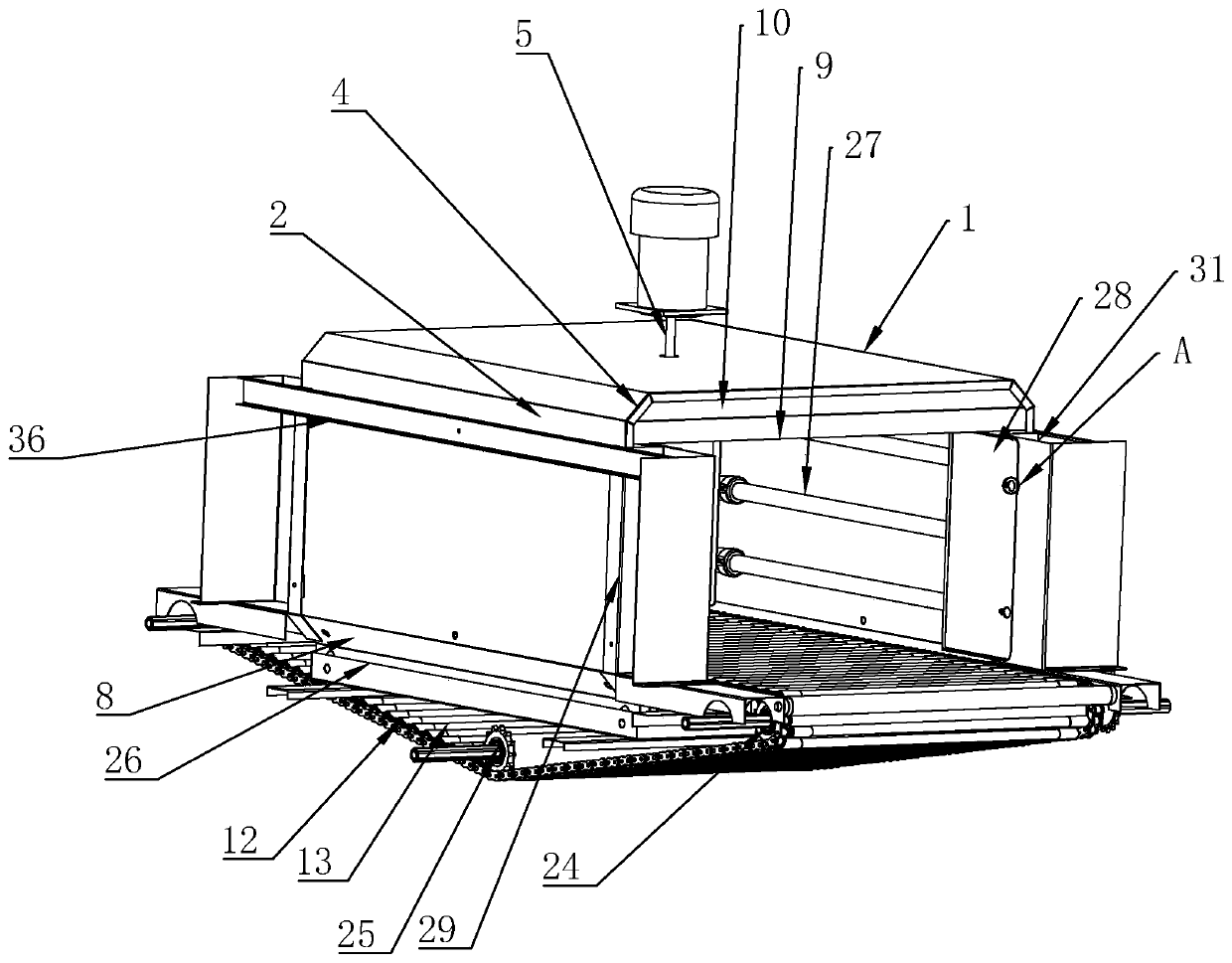
[0041] As a specific embodiment of the improvement, a second inclined plate 8 is provided on the side of the side mounting plate 2 facing away from the top plate 1, and the second inclined plate 8 is inclined toward the heat shrinkable space 3.

[0042] Through the arrangement of the second inclined plate 8, it is possible to make the air flow more smoothly under the guidance of the second inclined surface when the air flow passes under the heat shrink space 3, and further promote the uniform distribution of the hot air flow.

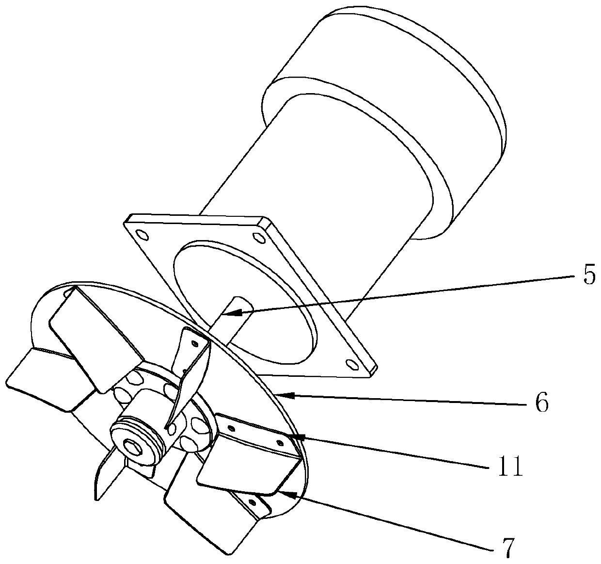
[0043] As an improved specific embodiment, the mounting plate 11 is fixed on the rotating disk 6.

[0044] Since the hot air flow will flow upward, the arrangement of the upper sealing plate 9 can block the hot air flow in the material conveying direction of the material conveying channel and avoid the loss of heat. At the same time, the arrangement of the third inclined plate 10 can play a role of diversion in the material conveying direction of the material ...

specific Embodiment approach

[0060] As an improved specific embodiment, a lower mounting plate 26 is provided below the side mounting plate 2. The lower mounting plate is located in the annular hollow formed by the transmission chain 12. The side mounting plate 2 and the lower mounting plate 26 A heater 27 is provided toward the heat shrink space 3, the side mounting plate 2 is provided with side baffles 28 at the entrance and exit of the transmission mechanism, and the heater 27 on the side mounting plate 2 is located at the entrance and exit of the transmission mechanism It is located between the side mounting plate 2 and the side baffle 28, leaving a gap between the side baffle 28 and the heater 27.

[0061] The lower mounting plate 26 is arranged in the annular hollow formed by the transmission chain 12, so that it can also play an additional role under the package transported on the transmission chain 12, so that the entire package can be completely heat-shrinked during the heat shrinking process . In ...


PUM


Abstract

The invention discloses a heat-shrinkage machine. The machine comprises a top plate; side mounting plates are arranged on two sides of the top plate; a heat-shrinkage space is formed by the top plate and the side mounting plates; a fan is arranged on the top plate; the top plate is connected with the side mounting plates through first inclined plates; the first inclined plates are inclined towards the heat-shrinkage space; the fan comprises a rotating shaft; a rotating disk is connected onto the rotating shaft; and a plurality of blades are arranged on the rotating disk, extend from the center of the rotating disk towards the outer edge of the rotating disk and are located inside the outer edge of the rotating disk. The machine has the beneficial effects as follows: the blades are arranged on the rotating disk and are located inside the outer edge of the rotating disk, up-and-down flowing of air flow in positions of the blades is well avoided by the aid of the rotating disk, unnecessary working is reduced to the greatest extent, the first inclined plates are arranged, hot air flow can be prevented from being accumulated in corners where the side mounting plates are connected with the top plate under the guiding effect of the first inclined plates in the heat accumulation process, and thus the optimal heat dispersing effect can be realized.

Description

Technical field [0001] The invention relates to a packaging equipment, more specifically to a heat shrinking machine. Background technique [0002] Heat shrinking machine, also called shrinking machine, heat shrinking packaging machine, is one of the more advanced packaging methods in the market. The shrink film is used to wrap the product or package outside, and the shrink film is heated to wrap the product or package tightly, fully showing the appearance of the item, improving the product's displayability, and increasing the beauty and sense of value. [0003] In the prior art, the Chinese patent with the application number CN96219912.5, a heat shrinking machine with a motor displacement, is composed of a lower furnace body, a furnace body, an insulation layer, a heating device, a hot air circulation device, and a conveyor belt. The circulation device is composed of a motor, a wind wheel or ceiling fan, a pulley, and a belt. The motor drives one or more wind wheels or ceiling fa...

Claims


Application Information

Patent Timeline
Patent Type & Authority Patents(China)
IPC IPC(8): B65B53/06
CPCB65B53/06
Inventor 厉勇
Owner ZHEJIANG DINGYE MACHINERY
Learn More