A pressure wheel flying coin mechanism

A roller mechanism, fly coin technology, applied in conveyors, optical testing flaws/defects, chute and other directions, can solve the problems of uneven transportation speed, change of coin output speed, slight rotation, etc., to achieve gradual friction resistance, friction resistance The effect of smooth change and reduction of rigid shock

Active Publication Date: 2018-10-19
NANJING CBPM GREAT WALL FINANCIAL EQUIP
View PDF5 Cites 0 Cited by
  • Summary
  • Abstract
  • Description
  • Claims
  • Application Information

AI Technical Summary

Problems solved by technology

Since the friction force of coins is not only affected by their own weight when sliding on the inclined slideway, but also affected by external humidity and other factors, uneven transportation speed and slight rotation may occur, resulting in changes in the output speed of coins

Method used


Image

  • A pressure wheel flying coin mechanism
  • A pressure wheel flying coin mechanism

Examples


Embodiment 1

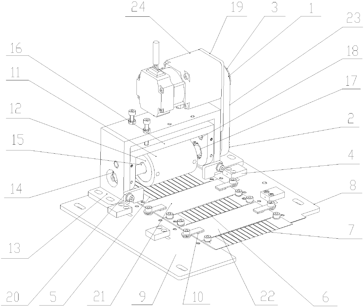
[0023] Such as figure 1 As shown, a pressure wheel flying coin mechanism includes a slideway and a roller mechanism installed at the outlet end of the conveyor belt; it also includes a first support plate 8 and a second support plate 9 arranged on both sides of the slideway; the slideway includes a spacer A ceramic slide plate and a glass slide plate are provided; the roller mechanism is arranged on the slideway, and the roller mechanism includes a roller 11 driven by a motor 24, and a certain gap is provided between the roller 11 and the slideway.

[0024] The roller mechanism of the present invention also includes an outer gantry frame 13 arranged on the first support plate 8 and the second support plate 9, the outer gantry frame 13 is connected with an inner gantry frame 16, and the inner gantry frame 16 is internally installed Roller 11 is arranged, and described roller 11 rotates on inner gantry frame 16 through rotating shaft 15, and described rotating shaft 15 passes th...

Embodiment 2

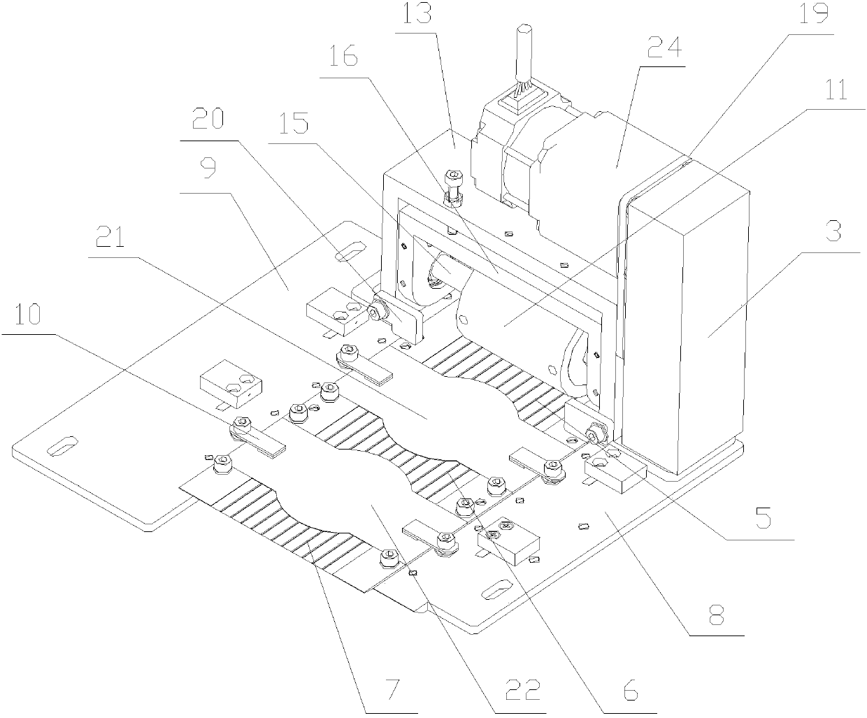
[0029] Such as figure 2 As shown, a pressure wheel flying coin mechanism includes a slideway and a roller mechanism installed at the outlet end of the conveyor belt; it also includes a first support plate 8 and a second support plate 9 arranged on both sides of the slideway; the slideway includes a spacer A ceramic slide plate and a glass slide plate are provided; the roller mechanism is arranged on the slideway, and the roller mechanism includes a roller 11 driven by a motor 24, and a certain gap is provided between the roller 11 and the slideway.

[0030] Both sides of the glass sliding plate of the present invention are symmetrically provided with arc-shaped transition blocks, and both sides of the ceramic sliding plate are provided with arc-shaped notches matching the arc-shaped transition blocks.

[0031] In order to effectively control and reduce the change of the sliding speed and sliding direction of the coin during the flying coin conveying, when designing the connec...


PUM


Abstract

The invention discloses a pressing wheel coin flying mechanism. The pressing wheel coin flying mechanism comprises a slideway and a roller mechanism which are installed at the outlet end of a conveying belt and further comprises a first support plate and a second support plate which are arranged on the two sides of the slideway. The pressing wheel coin flying mechanism is characterized in that the slideway comprises ceramic sliding boards and glass sliding boars which are arranged at intervals. The roller mechanism is arranged on the slideway and comprises a roller driven by a motor. A certain gap is reserved between the roller and the slideway. According to the pressing wheel coin flying mechanism, conveyed coins are subjected visual inspection through the two sets of glass sliding boards stably and reliably, and an adjusting mechanism of the polyurethane roller adopts inner and outer gantry frame structures and an adjustable eccentric locating mechanism. Groove structures are designed and machined for the ceramic sliding boards, thus damping of coin sliding is lowered effectively, and the rigid shock phenomenon in the coin moving process is reduced.

Description

technical field [0001] The invention relates to a press wheel flying coin mechanism. Background technique [0002] The commemorative coin inspection machine is used to check the quality and printing of coin stamping images, and generally includes a conveyor belt, an inclined slideway and a matching structure, wherein the inclined slideway is connected to the exit end of the conveyor belt, and the coins are transported from the conveyor belt to the inclined slideway For inertia and free fall, since the inclined slideway generally adopts a glass plate, when the coin is running on the inclined slideway, the front and back images of the coin can be taken simultaneously through the matching structure. Since the frictional force of coins is not only affected by their own weight when sliding on the inclined slideway, but also by external humidity and other factors, uneven transportation speed and slight rotation may occur, resulting in changes in the output speed of coins. Conten...

Claims


Application Information

Patent Timeline
Patent Type & Authority Patents(China)
IPC IPC(8): B65G11/20G01N21/89
CPCB65G11/203B65G2201/022G01N21/89
Inventor 虞纯洁李晓春
Owner NANJING CBPM GREAT WALL FINANCIAL EQUIP
Why Eureka
Try Eureka