Stepping conveying mechanism for lifting pipelines

A technology of stepping conveying and pipe fittings, applied in conveyors, transportation and packaging, etc., can solve the problems of injury to operators, increase in production cost, weak anti-vibration ability, etc., so as to avoid production waste and avoid production cost increase. Effect

Active Publication Date: 2017-02-22
CHONGQING KEBEN TECH
View PDF9 Cites 0 Cited by
  • Summary
  • Abstract
  • Description
  • Claims
  • Application Information

AI Technical Summary

Problems solved by technology

[0004] Therefore, the present invention proposes a step-by-step conveying mechanism for lifting pipe fittings, which solves the shortcomings of the traditional step-by-step conveying mechanism, such as poor anti-vibration ability, increased production cost and injury to operators caused by pipe fittings falling due to vibration.

Method used


Image

  • Stepping conveying mechanism for lifting pipelines
  • Stepping conveying mechanism for lifting pipelines
  • Stepping conveying mechanism for lifting pipelines

Examples


Embodiment Construction

[0017] The following will clearly and completely describe the technical solutions in the embodiments of the present invention with reference to the accompanying drawings in the embodiments of the present invention. Obviously, the described embodiments are only some, not all, embodiments of the present invention. Based on the embodiments of the present invention, all other embodiments obtained by persons of ordinary skill in the art without creative efforts fall within the protection scope of the present invention.

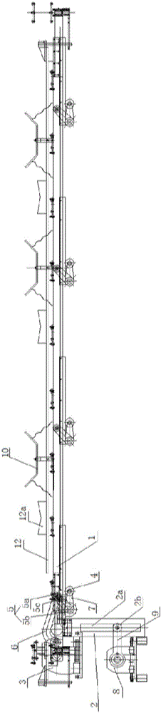
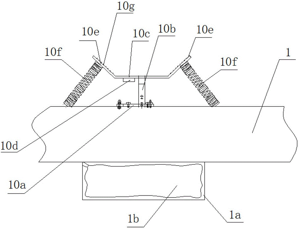
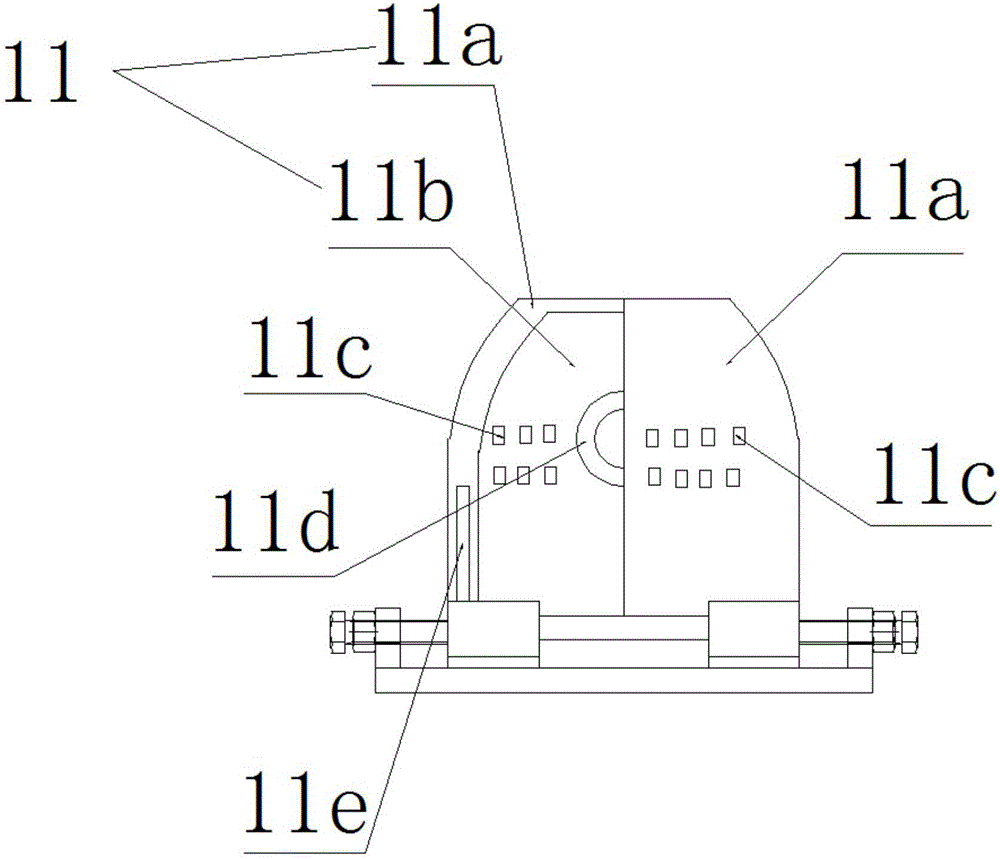
[0018] Such as Figures 1 to 3As shown, the step-by-step conveying mechanism for lifting pipes includes a conveying frame 1, a moving adjustment block 2, a lifting motor 3, a lifting fulcrum shaft 4, a lifting wheel 5, a lifting crank arm 6 and a connecting arm 7. The frame 1 is arranged horizontally and can move back and forth along the length direction of the transport frame 1. A translation motor 8 is installed horizontally on the lower side of the transport fra...


PUM


Abstract

The invention provides a stepping conveying mechanism for lifting pipelines. Each lifting support comprises a bottom plate, a supporting rod which is vertically arranged on the bottom plate, a supporting plate which is arranged at the top of the supporting rod and a vibration sensor which is arranged at the bottom of the supporting plate, wherein baffles are respectively arranged at two ends of the supporting plate in the length direction, and are arranged outward obliquely; a compression spring is arranged between each baffle bottom and a conveying rack, and is axially vertical to the baffle bottom. The stepping conveying mechanism has the beneficial effects that, an accommodating space is formed by the supporting plate and the baffles, and pipelines can be transversely placed in the accommodating space, the center axis of a pipeline, vertical to the length direction of the conveying rack, is horizontally placed in the accommodating space, the baffles are used for preventing pipelines from falling down and are matched with the compression springs, so that instant impact of the gravity of the pipeline on the conveying rack can be damped, and vibration can be absorbed in the process of supporting and placing pipelines.

Description

technical field [0001] The invention relates to transport equipment for tubular material parts, in particular to a step-by-step conveying mechanism for lifting pipe parts. Background technique [0002] When pipe fittings need to be transported horizontally, horizontal pipe fitting transport machinery is required. Most of the horizontal transport machinery used to transport pipe fittings at the beginning is a chain conveyor or a grate rolling structure. This traditional machine is only suitable for small diameters. When the large-diameter columnar pipe is transported horizontally, the equipment or the pipe itself will be damaged due to too much impact, and there are still unsafe factors in the operation process. [0003] In response to this, a new step-by-step conveying mechanism has emerged, which is equipped with lifting motors, moving adjustment blocks, lifting motors, lifting fulcrum shafts, lifting wheels, lifting crank arms, connecting arms, and translational motors. I...

Claims


Application Information

Patent Timeline
IPC IPC(8): B65G25/02
CPCB65G25/02
Inventor 朱兴德
Owner CHONGQING KEBEN TECH
Why Eureka
Try Eureka