Production method of glass cover plate, glass cover plate and mobile terminal
A technology of a glass cover plate and a manufacturing method, which is applied to the production of glass cover plates, the field of glass cover plates and mobile terminals, can solve problems such as bubbles and wrinkles, achieve good visual effects, solve wrinkles and bubbles, and meet appearance requirements.
- Summary
- Abstract
- Description
- Claims
- Application Information
AI Technical Summary
Problems solved by technology
Method used
Image
Examples
no. 1 example
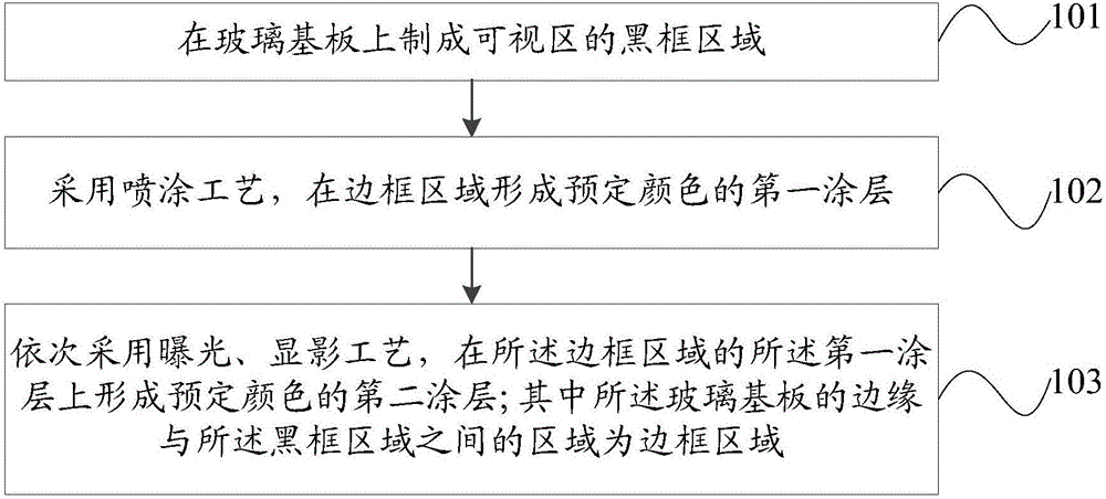
[0021] Such as figure 1 As shown, it is a flow chart of the manufacturing method of the glass cover plate in the first embodiment of the present invention. The implementation process of the manufacturing method of the glass cover plate will be specifically described below in conjunction with the figure.
[0022] Step 101 , forming a black frame area of a visible area on a glass substrate.
[0023] Here, the glass substrate may be a 2D glass substrate, a 2.5D glass substrate, or a 3D glass substrate.
[0024] The visible area refers to the area where the user can touch the screen to operate after the glass cover manufactured by the manufacturing method of the glass cover of the present invention is installed on the mobile terminal.
[0025] Step 102, using a spraying process to form a first coating of a predetermined color on the frame area.
[0026] Here, the frame area includes a predetermined opening area, such as an earpiece hole, a front camera hole, and the like. It...
no. 2 example
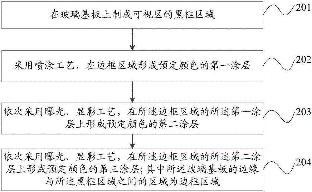
[0032] Such as figure 2 As shown, it is a flow chart of the manufacturing method of the glass cover plate in the second embodiment of the present invention. The implementation process of the manufacturing method of the glass cover plate will be specifically described below in conjunction with the figure.
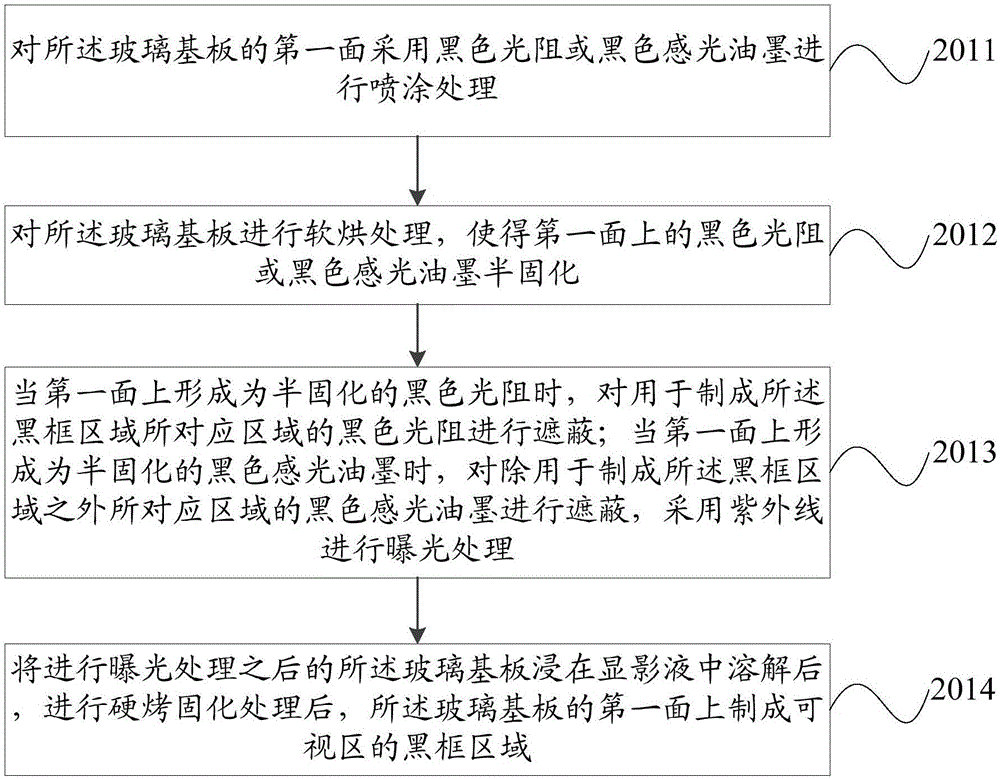
[0033] Step 201, forming a black frame area of a visible area on a glass substrate.
[0034] Here, the glass substrate may be a 2D glass substrate, a 2.5D glass substrate, or a 3D glass substrate. Embodiments of the present invention are aimed at a 3D hyperboloid glass substrate.
[0035] The visible area refers to the area where the user can touch the screen to operate after the glass cover manufactured by the manufacturing method of the glass cover of the present invention is installed on the mobile terminal.
[0036] Step 202, using a spraying process to form a first coating of a predetermined color on the frame area.
[0037] Here, the frame area includes a predet...
no. 3 example
[0078] An embodiment of the present invention provides a glass cover plate, which is manufactured by the manufacturing method in the above embodiment. A black frame area covered with a visible area and a frame area with a predetermined color are sequentially formed on the glass cover;
[0079] Wherein the frame area is an area between the edge of the glass cover plate and the black frame area.
[0080] The glass cover plate provided by the embodiment of the present invention is a glass cover plate with a specific color and a specific texture. Wrinkles and air bubbles that are easy to occur during the coloring process of the cover plate pasting the color film.
PUM
 Abstract
Description
Claims
Application Information
 - R&D
- Intellectual Property
- Life Sciences
- Materials
- Tech Scout
- Unparalleled Data Quality
- Higher Quality Content
- 60% Fewer Hallucinations
Browse by: Latest US Patents, China's latest patents, Technical Efficacy Thesaurus, Application Domain, Technology Topic, Popular Technical Reports.
© 2025 PatSnap. All rights reserved.Legal|Privacy policy|Modern Slavery Act Transparency Statement|Sitemap|About US| Contact US: help@patsnap.com


