
Washing machine

A washing machine and inner drum technology, applied in the field of washing machines, can solve problems such as splashing of clothes, excessive water volume, and limited washing ability of clothes, and achieve the effects of reducing process complexity and production costs, washing clothes evenly, and improving cleaning quality

Active Publication Date: 2017-02-22
WUXI LITTLE SWAN ELECTRIC CO LTD
View PDF8 Cites 7 Cited by
  • Summary
  • Abstract
  • Description
  • Claims
  • Application Information

AI Technical Summary

Problems solved by technology

However, the structure design of the lower plate of the balance ring of the pulsator washing machine in the related art is unreasonable. The water volume is small, and the phenomenon of uneven water flow distribution is very serious, and the excessive water flow is not conducive to the normal intersection of the sprayed water flows at both ends, resulting in a small flow and weak sheet-like water flow in the middle, and the intersection is a high jet height. , The strong columnar water flow makes the cleaning ability of the clothes limited, and the excessively high columnar water flow is easy to hit the clothes and cause water splashing, which is not conducive to ensuring the safety of the washing machine line and the sanitation inside the drum

Method used


Image

  • Washing machine
  • Washing machine
  • Washing machine

Examples


Embodiment Construction

[0056] The following describes in detail the embodiments of the present invention, examples of which are illustrated in the accompanying drawings. The embodiments described below with reference to the accompanying drawings are exemplary, and are intended to explain the present invention and should not be construed as limiting the present invention.

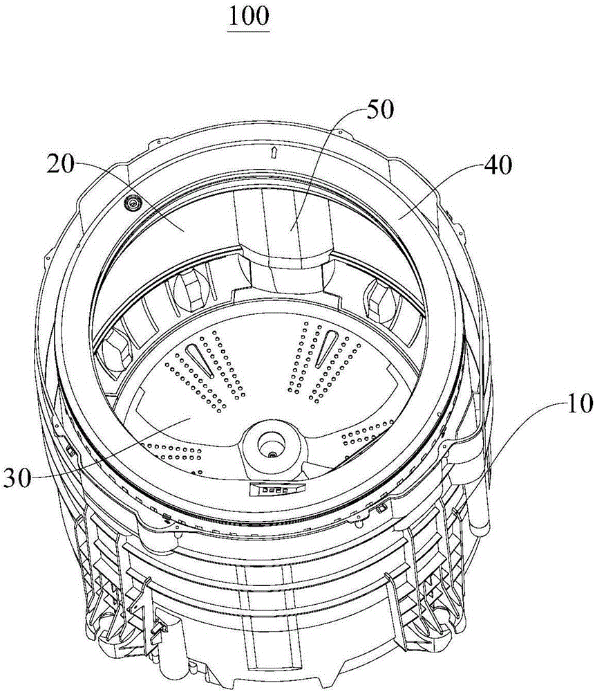
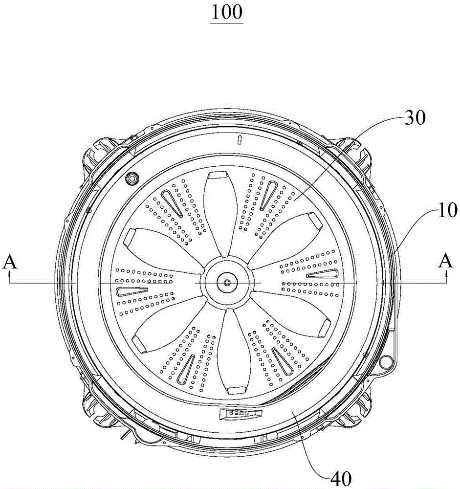
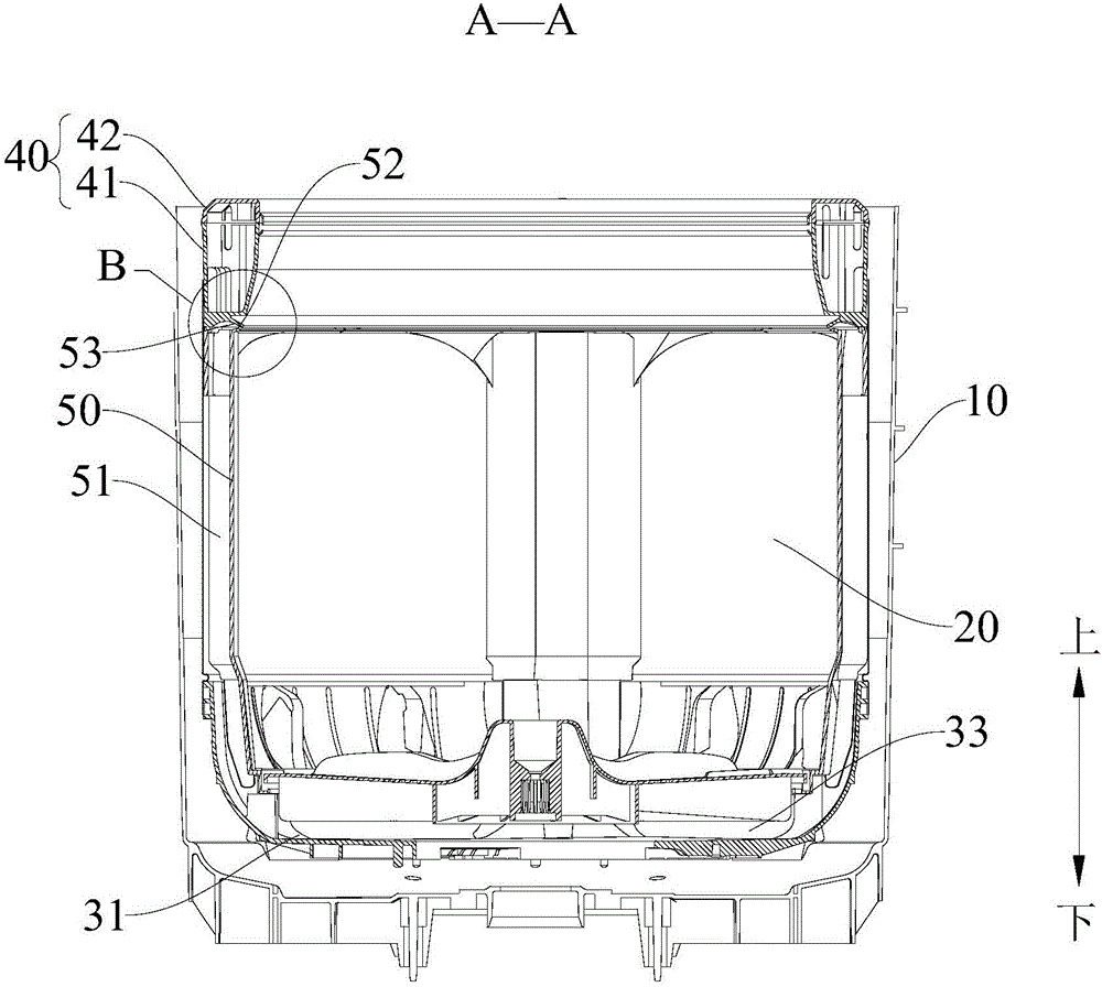
[0057]Attached below Figure 1 to Figure 15 The washing machine 100 according to the embodiment of the present invention is described in detail.

[0058] The washing machine 100 according to the embodiment of the present invention includes an outer tub 10 , an inner tub 20 , a pulsator 30 and a balance ring assembly 40 . Specifically, the inner cylinder 20 is arranged in the outer cylinder 10 and is spaced apart from the outer cylinder 10 , and the inner side wall of the inner cylinder 20 is provided with a plurality of water passage plates 50 which are spaced apart along the circumference thereof, and each water passage passage ...


PUM

PropertyMeasurementUnit
Size of the openingaaaaaaaaaa

Abstract

The invention discloses a washing machine. The washing machine comprises an inner cylinder, an outer cylinder, a corrugated disk and a balance ring component. The inner cylinder is located within the outer cylinder with an interval in between. A plurality of water flow plates are placed at regular intervals along the circumference of the inner side wall of the inner cylinder. Each water flow plate and the inner side wall of the inner cylinder constitute a water flow path. The corrugated disk is located at the bottom of the inner cylinder. The corrugated disk and the inner cylinder bottom constitute a water segregation cavity. The water segregation cavity is communicated with the water flow path. The side of the corrugated disk away from the water segregation cavity is placed with water discharge rib. The balance ring component is placed on the upper side. The balance ring component and the upper ends of a plurality of water flow paths constitute a plurality of flow spray cavity. Each flow spray flow cavity is communicated with the water flow path. A plurality of water separation guide ribs placed at regular intervals are located in each flow spray cavity. The inner circle of the upper end of each water flow path and the inner circle edge of the lower end of balance ring component constitute spray blast mouths. The washing machine has the advantage of simple structure, low production cost, high safety, average water output and high clean ratio.

Description

technical field [0001] The present invention relates to the technical field of washing machines, and more particularly, to a washing machine. Background technique [0002] At present, the pulsator washing machine mainly displaces the water flow through the rotation of the pulsator during washing, so that the water flow rises to the top jet flow cavity through the water flow channel plate, and is sprayed back into the inner cylinder from the jet flow port, so as to strengthen the cleaning of the clothes. However, the design of the lower plate structure of the balance ring of the pulsator washing machine in the related art is unreasonable, and the flow rate to both sides after the rising water enters the top water spray channel cavity is too large, resulting in excessive water volume at both ends of the cavity, and the middle area is too large. The water volume is small, and the uneven distribution of water flow is very serious, and the excessive water flow is not conducive to...

Claims


Application Information

Patent Timeline
IPC IPC(8): D06F17/06D06F17/04D06F39/08D06F37/26
CPCD06F17/04D06F17/06D06F37/268D06F39/083
Inventor 周鹏邓德喜李磊周福昌孔凡实
Owner WUXI LITTLE SWAN ELECTRIC CO LTD
Learn More