Washing machine

A technology for washing machines and washing tubs, applied in the field of washing machines, which can solve the problems of bacteria breeding, the inability to disassemble and clean the inner and outer tubs, and dirt storage, and achieve the effects of saving materials, avoiding bacterial growth, and saving water

Inactive Publication Date: 2017-02-22
WUXI LITTLE SWAN CO LTD
View PDF9 Cites 12 Cited by
  • Summary
  • Abstract
  • Description
  • Claims
  • Application Information

AI Technical Summary

Problems solved by technology

The most important thing is that ordinary users cannot disassemble and clean the inner and outer barrels. After a long period of use, there will be dirt and bacteria between the inner and outer barrels.

Method used


Image

  • Washing machine
  • Washing machine
  • Washing machine

Examples


Embodiment 1

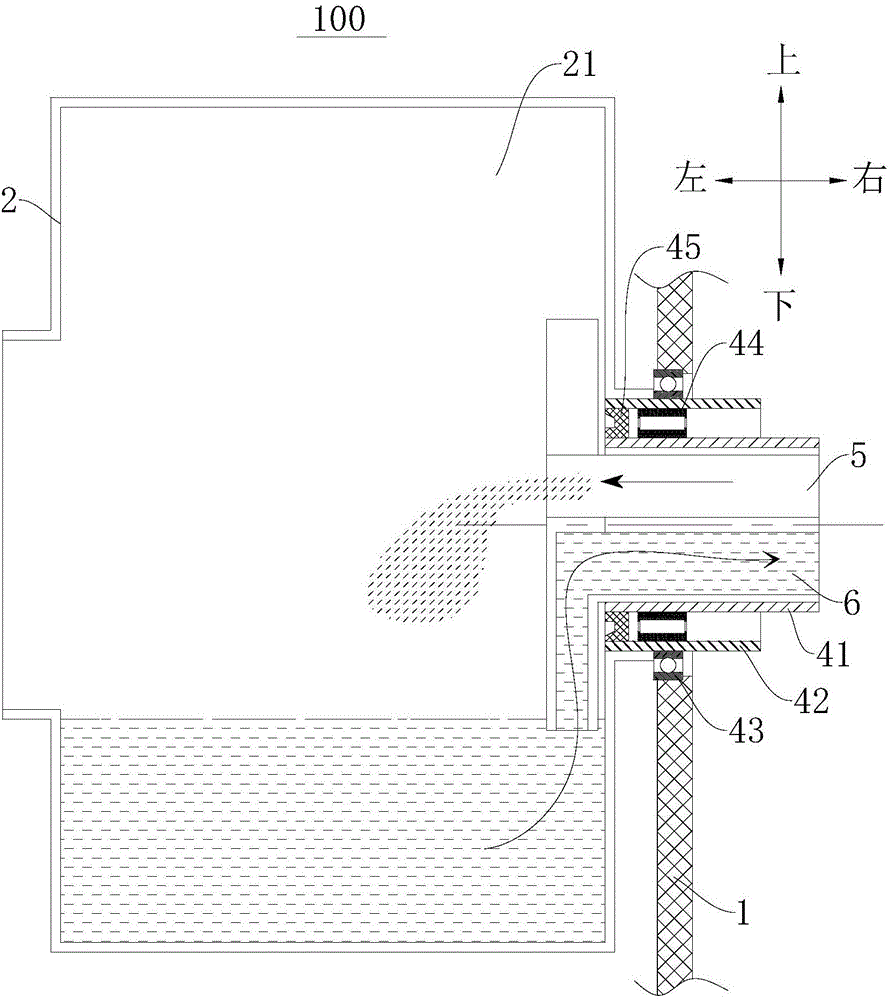
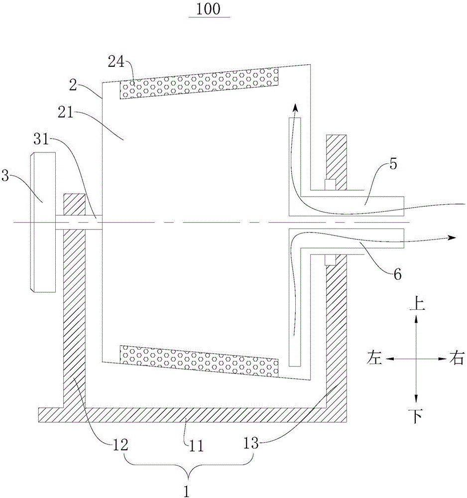
[0113] refer to figure 1 , the washing machine 100 includes a base 1 , a washing tub 2 , a driving member 3 , a support assembly 4 , a water inlet pipe 5 , a drain pipe 6 , a heating device 7 , a pump 8 and a locking device 9 .

[0114] Specifically, as figure 1 As shown, the base 1 may include: a bottom plate 11, a first bracket 12 and a second bracket 13, wherein the first bracket 12 and the second bracket 13 extend along the up-down direction and are arranged at intervals along the left-right direction on the bottom plate 11, washing The tub 2 is rotatably provided between the first bracket 12 and the second bracket 13 .

[0115] The washing bucket 2 is a hollow column extending along the left and right direction. A washing cavity 21 is formed in the washing bucket 2, and the left end of the washing bucket 2 is closed and a through hole is formed in the center of the right end. In the direction from left to right, the washing bucket The diameter of the washing tub 2 incre...

Embodiment 2

[0131] The structure of this embodiment is substantially the same as that of Embodiment 1, wherein the same components use the same reference numerals, the difference is only that: the washing machine 100 in Embodiment 1 includes a pump 8 and a heating device 7, while in Embodiment 2 The washing machine 100 described above only includes a heating device 7 and does not include a pump 8. The heating device 7 is arranged outside the washing tub 2 and only heats the water flowing through the water inlet pipe 5 when the water enters.

Embodiment 3

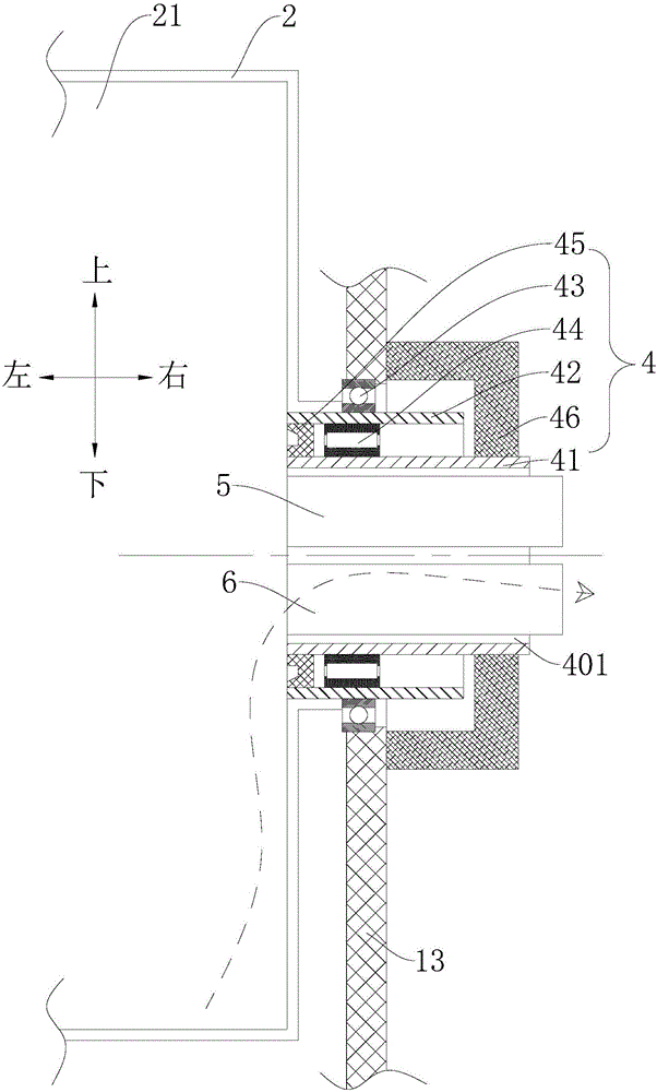
[0133] The structure of this embodiment is substantially the same as that of Embodiment 1, wherein the same components use the same reference numerals, the only difference is that: the washing machine 100 in Embodiment 1 includes a pump 8 and a heating device 7, and the heating device 7 is set Outside the washing tub 2, the washing machine 100 in the third embodiment only includes the heating device 7 and does not include the pump 8, and the heating device 7 is arranged inside the washing tub 2 for directly heating the water in the washing chamber 21 . And the heating power line 71 of the heating device 7 passes through the pipeline channel 401 and extends out of the washing chamber 21 .


PUM


Abstract

The invention discloses a washing machine. The washing machine comprises a pedestal, a washing cylinder, a drive component, a water inlet pipe and a water outlet pipe. The washing cylinder is rotationally mounted on the pedestal through a central shaft rotating levelly. A washing cavity is formed in the washing cylinder. One end of the water inlet pipe extends into the washing cavity. The other end of the water inlet pipe protrudes out of the washing cavity. One end of the water inlet pipe is provided with a nozzle extending upward. The nozzle resembles a central hollow tube sealed at the upper end. A plurality of water spray mouths are formed on the circumferential wall of the nozzle. One end of the water discharge pipe extends into the washing cavity, and the other end of the water discharge pipe protrudes out of the washing cavity. At least a portion of one end of the water discharge pipe extends downward vertically. A plurality of water discharge holes are placed at the lower end of the water discharge pipe. The output shaft of the drive component is connected with the washing cylinder in a relatively fixed mode. The drive component is used to drive the rotation of the washing cylinder. The washing machine can achieve single cylinder washing, save material, save water, lower cost. The washing machine has the advantage of preventing bacteria growth and making the environment of the washing machine clean.

Description

technical field [0001] The invention relates to the technical field of household appliances, in particular to a washing machine. Background technique [0002] The washing machine in the related art, no matter the drum washing machine or the pulsator washing machine, its internal structure is supported and fixed by a relatively fixed outer tub and a rotatable inner tub for washing and dehydrating clothes. When washing and rinsing, tap water is poured into the barrel, because the inner and outer barrels need to rotate relatively, so there must be a gap between the inner and outer barrels, in the actual washing or rinsing process, because the tap water will fill the gap between the inner and outer barrels, making the actual use The amount of water is much more than what the user can see in the inner bucket. In today's increasingly scarce water resources, realizing the purpose of saving water through technical means has become a new innovation growth point that various related ...

Claims


Application Information

Patent Timeline
Patent Type & Authority Applications(China)
IPC IPC(8): D06F23/02D06F37/06D06F37/36D06F39/08D06F39/04D06F37/22
CPCD06F23/025D06F37/06D06F37/22D06F37/36D06F39/04D06F39/083D06F39/085D06F39/088
Inventor 俞燕金炅学
Owner WUXI LITTLE SWAN CO LTD
Why Eureka
Try Eureka