Method and Device for Removing Pollution From a Confined Environment

a technology for confined environments and cleaning methods, applied in mechanical equipment, pipe heating/cooling, transportation and packaging, etc., can solve the problems of plastic walls that cannot withstand differential pressure greater than a few tens of atmospheres, and walls that cannot withstand significant differences in pressur

Active Publication Date: 2009-10-22
PFEIFFER VACUUM GMBH
View PDF4 Cites 10 Cited by
  • Summary
  • Abstract
  • Description
  • Claims
  • Application Information

AI Technical Summary

Benefits of technology

[0075]The analysis of the composition of the gas mixture found within the enclosed environment may, in particular, make it possible to determine the origin of a contamination, and therefore the step of the method which was responsible for it (the location where the photomask or a semiconductor wafer was manufactured, transportation, storage area, etc.).
[0076]This analysis may also make it possible to monitor the quality of the enclosed environments, in order to establish real-time diagnostics and, if need be, to clean these enclosed environments.

Problems solved by technology

This is because these walls are unable to withstand significant differences in pressure without degrading: for a photomask, the film cannot withstand a difference in pressure greater than about 1 Pa; for currently used atmospheric transport pods, the plastic walls cannot withstand a differential pressure greater than a few tens of atmospheres.

Method used


Image

  • Method and Device for Removing Pollution From a Confined Environment
  • Method and Device for Removing Pollution From a Confined Environment
  • Method and Device for Removing Pollution From a Confined Environment

Examples


first embodiment

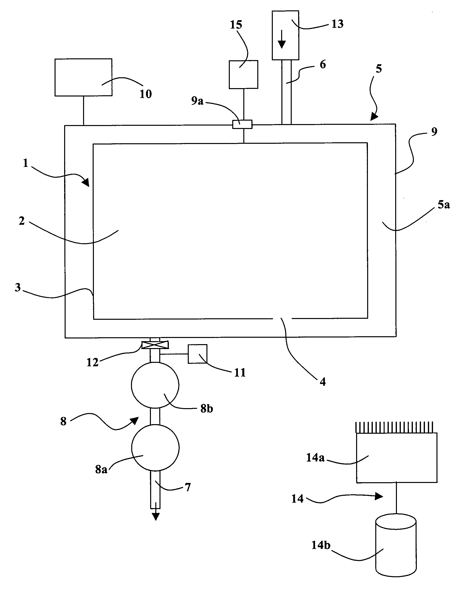
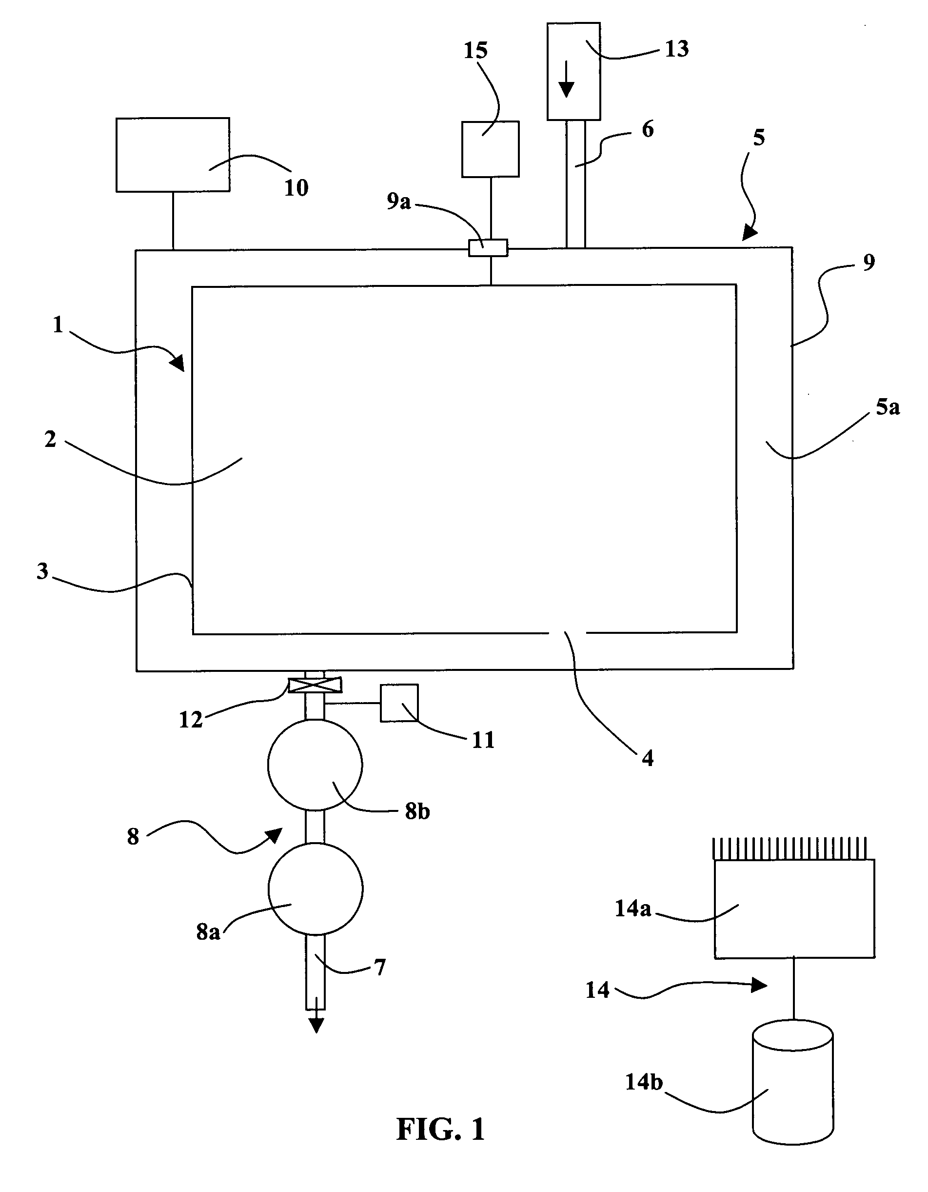
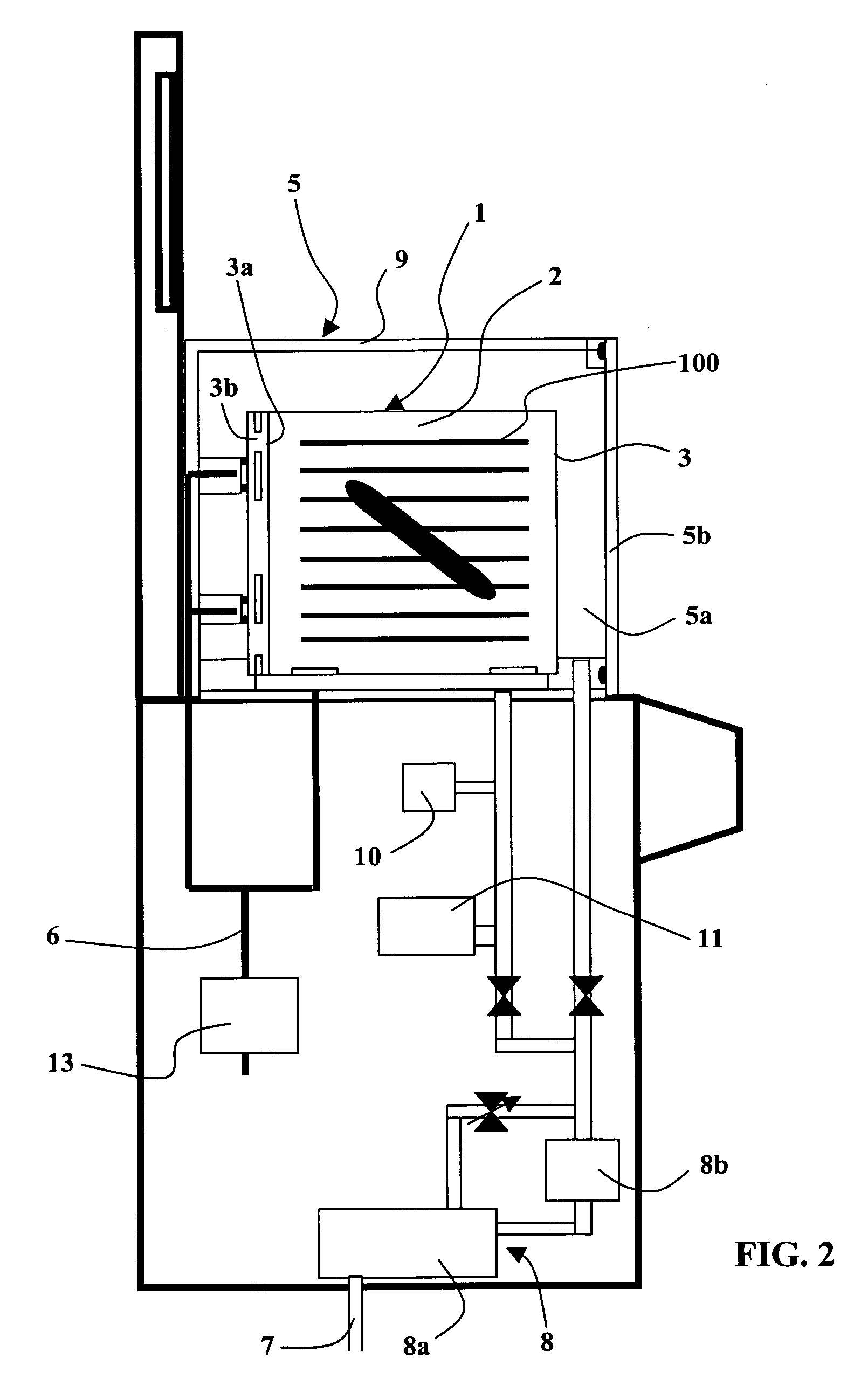
[0100]In the invention depicted in FIG. 2, a cross-section is shown of a device for decontaminating an unsealed enclosed environment 1, which is an atmospheric transport pod and / or substrate wafer storage pod, having an inner volume 2 delimited by a side wall 3 equipped with an access hole 3a that may be blocked by a door 3b, and which makes it possible to add or remove a stack of substrate wafers 100. A decontamination chamber 5, which may be twice as voluminous as the unsealed enclosed environment 1 which is placed therein, is distinguished, and is connected to purging gas injection means 6, 13, gas pumping means 7, 8, pressure measurement means 10 for measuring the gas pressure within the decontamination chamber 5, and means for controlling the difference in pressure between the interior and exterior of the transport pod 1.

[0101]The inventive method is particularly well-suited to atmospheric transport pods 1, whose plastic structure cannot withstand differences in pressure which ...

second embodiment

[0133]Now we shall consider FIG. 3, which detects a second embodiment in accordance with the invention. The inventive method is here applied to a situation wherein the unsealed enclosed environment 1 is a photomask equipped with its film. The enclosed environment comprises the volume 2 between its wall 3, constituted by the film, and the active surface 32 of the photomask that it covers. Openings 35 with low-conductance filters are located on the edge of the unsealed enclosed environment 1.

[0134]A decontamination chamber 5 may contain one or more photomasks 1. The decontamination chamber 5 may itself be a transport pod, or may be the transport pod attached to a small additional volume 5c which makes it possible to open the transport pod, or the decontamination chamber may be a separate pod. If there are multiple photomasks 1, they are stacked inside a carrier 33 which is placed inside a sealed, low-volume decontamination chamber 5. It is preferable that the decontamination chamber 5...


PUM

PropertyMeasurementUnit
pressureaaaaaaaaaa
temperatureaaaaaaaaaa
volumeaaaaaaaaaa

Abstract

The subject of the present invention is a method for removing pollution from a confined environment containing an interior space bounded by a wall, involving the following steps:
    • the confined environment which has a leak is placed in a sealed chamber comprising means of introducing a gas and means of pumping a gas
    • the gas contained in the chamber and the gas contained inside the space are simultaneously pumped through the leak so that the pressure difference across the wall is always below a wall-damaging threshold.
    • Another subject of the invention is a device for removing pollution from a confined environment comprising:
      • a pollution removal chamber able to contain the confined environment,
      • means of introducing a purging gas,
      • means of pumping a gas with variable pumping capacity,
      • means for controlling the pumping rate,
      • means for monitoring the pressure difference between the inside and the outside of the environment.
    • mechanical warping that would damage the wall of the unsealed enclosed environment.

Description

TECHNICAL FIELD OF THE INVENTION[0001]The invention pertains to the cleaning and depollution of unsealed confined environments, particularly including storage and transport pods for semiconductor substrates, agrifood products, medical or automobile products, or photomasks equipped with their protective films.[0002]Storage and transport pods under atmospheric pressure for one or more substrates, particularly for semiconductor wafers, define an enclosed space, separated from the environment in which the substrates are used and transported by a peripheral wall equipped with an opening through which subtrates may pass, covered by a door. This type of transport pod is most commonly made of plastic and is not generally sealed when in service. The plastic peripheral wall is not designed to withstand pressures greater than a few tens of atmospheres without sustaining damage. The transport pods are therefore designed with at least one leak, so that when a difference in pressure exists betwee...

Claims


Application Information

Patent Timeline
Patent Type & Authority Applications(United States)
IPC IPC(8): H01L21/00H01L21/673
CPCH01L21/67017H01L21/67389H01L21/67253Y10T137/0419Y10T137/6579H01L21/67109H01L21/67201
Inventor FAVRE, ARNAUDBELLET, BERTRANDBERNARD, ROLANDMETAIS, XAVIER
Owner PFEIFFER VACUUM GMBH
Why Eureka
Try Eureka