Natural gas mixer
A natural gas and mixer technology, which is applied in the direction of machines/engines, oil supply devices, internal combustion piston engines, etc., can solve the problems of poor mixed gas flow, low mixing uniformity, and small space in the pressure stabilizing chamber, etc., to achieve the mixing effect Good, high mixing uniformity, and large space in the stabilizing chamber
- Summary
- Abstract
- Description
- Claims
- Application Information
AI Technical Summary
Problems solved by technology
Method used
Image
Examples
Embodiment 1
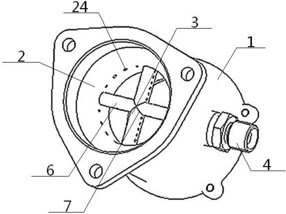
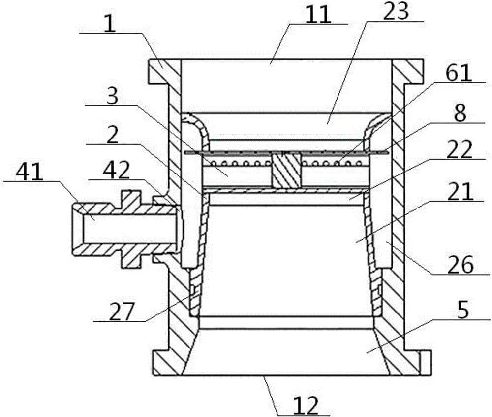
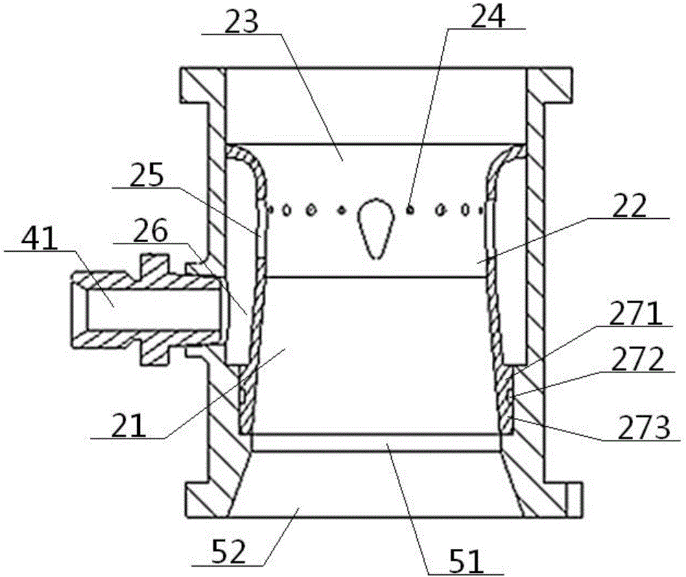
[0055] see Figure 1 to Figure 8 , a natural gas mixer, comprising an outer shell 1, an inner cavity 2 and an air cavity 3, the outer shell 1 is provided with a coaxial inner cavity 2, and the inner cavity 2 is provided with an air cavity 3. Both the air cavity body 3 and the inner cavity body 2 communicate with the air intake unit 4 provided on the side wall of the outer casing 1, and the inner cavity body 2 communicates with the air inlet unit 5 arranged on the bottom of the outer casing 1;
[0056] The inner cavity 2 is a hollow waist-shaped body structure, which includes an air inlet part 21, a mixing part 22, and a mixed gas outlet part 23 connected in sequence from bottom to top. The air inlet part 21 is a cone with a narrow top and a wide bottom. Platform structure, the side wall of the mixing part 22 is provided with an inner cavity natural gas injection hole 24 and an inner air cavity connecting hole 25, and the mixed gas outlet 23 is a frustum structure with a narrow...
Embodiment 2
[0058] Basic content is the same as embodiment 1, the difference is:
[0059] The mixed gas outlet portion 23 includes a lower narrow portion 231, a transition portion 232 and an outer wide portion 233, and the mixing portion 22 communicates with the housing gas outlet 11 after passing through the lower narrow portion 231, the transition portion 232, and the outer wide portion 233 in sequence. The transition part 232 is an outwardly expanding circular arc structure extending upward, and the periphery of the outer wide part 233 is in sealing fit with the part near the top of the inner wall of the outer casing 1 .
Embodiment 3
[0061] Basic content is the same as embodiment 1, the difference is:
[0062] The air intake unit 4 includes an air intake joint 41 and an air intake 42 provided on the side wall of the outer casing 1. The air intake joint 41 communicates with the natural gas pressure stabilizing chamber 26 after the air intake 42, and the air intake 42 is set lower than the junction of the air intake part 21 and the mixing part 22. The air inlet unit 5 includes a coaxial upper air inlet part 51 and a lower air inlet part 52. The air inlet part 21 communicates with the housing air inlet 12 after passing through the upper air inlet part 51 and the lower air inlet part 52 in sequence. The air part 51 is a cylindrical structure, and the lower air inlet part 52 is a truncated cone structure with a narrow top and a wide bottom.
PUM
 Abstract
Description
Claims
Application Information
 - R&D
- Intellectual Property
- Life Sciences
- Materials
- Tech Scout
- Unparalleled Data Quality
- Higher Quality Content
- 60% Fewer Hallucinations
Browse by: Latest US Patents, China's latest patents, Technical Efficacy Thesaurus, Application Domain, Technology Topic, Popular Technical Reports.
© 2025 PatSnap. All rights reserved.Legal|Privacy policy|Modern Slavery Act Transparency Statement|Sitemap|About US| Contact US: help@patsnap.com


