Eureka AIR delivers breakthrough ideas for toughest innovation challenges, trusted by R&D personnel around the world.

Small hydraulic power generating system

A technology of small-scale hydroelectric power generation and water trucks, which is applied in the direction of hydropower generation, hydropower stations, and water conservancy projects. It can solve the problems of bulky power generation equipment, large floor space, and large water consumption, and achieve high utilization of water resources. The effect of small footprint and small water loss

Inactive Publication Date: 2017-02-22
贵州乡村水电新能源开发有限公司
View PDF9 Cites 0 Cited by
  • Summary
  • Abstract
  • Description
  • Claims
  • Application Information

AI Technical Summary

Problems solved by technology

[0002] Due to the structure of the power generation equipment and the installation pattern, the existing hydroelectric power generation system needs a large water flow to provide sufficient power for power generation. Therefore, it is necessary to build a dam or build a large reservoir for water storage, and its location is difficult. It occupies a large area, consumes a lot of water, and the power generation equipment is bulky and complex in structure and high in cost

Method used


Image

  • Small hydraulic power generating system
  • Small hydraulic power generating system
  • Small hydraulic power generating system

Examples


Embodiment Construction

[0018] The present invention will be further described below in conjunction with accompanying drawing and specific embodiment:

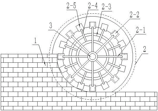
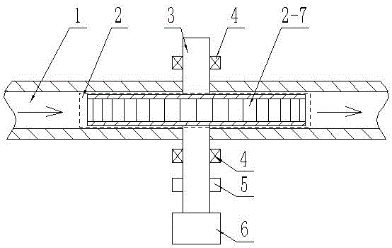
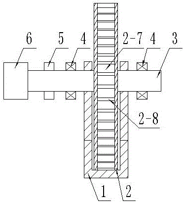
[0019] Such as Figure 1~5 Shown: a small-scale hydroelectric power generation system, including a water channel 1, a waterwheel 2 connected to a coupling 5 and a generator 6 through a rotating shaft 3, the water channel is a "Z" shaped structure, and the water channel is a "Z" shaped structure, The lower part of the waterwheel 2 is tangent to the bottom surface of the canal 1 or has a small gap, and the width of the waterwheel 2 is slightly smaller than the width of the canal, preferably the gap is 0.5-1 cm, and the width of the waterwheel is slightly smaller than the width of the canal, and the width difference is preferably 0.5-1 cm. Said waterwheel 2 is a ring-shaped structure composed of front and rear two waterwheel sides 2-9 and bottom edge 2-10, several "V"-shaped water buckets 2-7 installed in the ring-shaped structure, and radially arranged...


PUM


Abstract

The invention relates to a small hydraulic power generating system and belongs to the technical field of power generating equipment. The small hydraulic power generating system comprises a canal 1 and a water wagon 2 which is connected with a shaft coupling 5 and a generator 6 through a rotating shaft 3; the canal is of a Z-shaped structure; the lower part of the water wagon 2 is tangent with the bottom of the canal 1, or a relatively small gap is formed between the lower part of the water wagon 2 and the bottom of the canal 1, and the width of the water wagon 2 is slightly smaller than that of the canal; and the water wagon 2 is composed of an annular structure, a plurality of V-shaped buckets 2-7 and supporting net racks 2-1, the annular structure is composed of front and rear water wagon side edges 2-9 and a bottom edge 2-10, the plurality of V-shaped buckets 2-7 are mounted in the annular structure, and the supporting net racks 2-1 are radially arranged outside a rotating shaft 3 and are respectively connected to the front and rear water wagon side edges 2-9 through connecting blocks 2-2. The small hydraulic power generating system is simple and compact in structure, small in floor area, low in cost, needless of water storage, capable of generating power at a relatively small water flow, relatively low in water resource demand, free of strict requirements for site selection, capable of implementing at the edge of a relatively small canal and favorable in market prospect.

Description

technical field [0001] The invention relates to a small hydroelectric power generation system and belongs to the technical field of power generation equipment. Background technique [0002] Due to the structure of the power generation equipment and the installation pattern, the existing hydroelectric power generation system needs a large water flow to provide sufficient power for power generation. Therefore, it is necessary to build a dam or build a large reservoir for water storage, and its location is difficult. It occupies a large area, consumes a lot of water, and the power generation equipment is bulky and complex in structure, and the cost is high. Contents of the invention [0003] In order to overcome the defects existing in the prior art, the object of the present invention is to provide a small hydroelectric power generation system with simple and compact structure, small footprint, low cost, no need for water storage, and capable of generating electricity under ...

Claims


Application Information

Patent Timeline
Patent Type & Authority Applications(China)
IPC IPC(8): F03B13/00F03B1/02F03B11/00F03B11/06E02B9/04
CPCF03B1/02F03B11/00F03B11/06F03B13/00E02B9/04F05B2220/706Y02E10/20
Inventor 王成锦
Owner 贵州乡村水电新能源开发有限公司
Why Eureka
Eureka Blog
Learn More