Control method for radial magnetic bearing
A control method and technology of magnetic bearing, applied in the field of magnetic bearing, can solve the problems of poor performance of suppressing impact disturbance of magnetic bearing, large magnetic leakage of radial magnetic bearing with large air gap, etc., so as to increase suspension force, reduce magnetic leakage, and improve stability sexual effect
- Summary
- Abstract
- Description
- Claims
- Application Information
AI Technical Summary
Problems solved by technology
Method used
Image


Examples
Embodiment 1
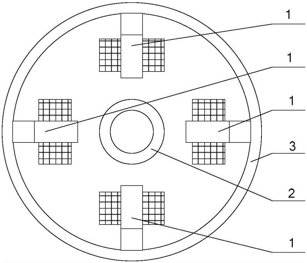
[0075] Embodiment 1: as figure 1 As shown, the large-gap radial magnetic bearing of the divided stator in this embodiment includes four stators 1 and rotor cores 2; the four stators 1 are evenly distributed around the rotor core 2 along the circumferential direction, and the four stators 1 There is no closed magnetic circuit between them; there is a radial air gap between each stator 1 and the rotor core 2, and a closed magnetic circuit is formed.
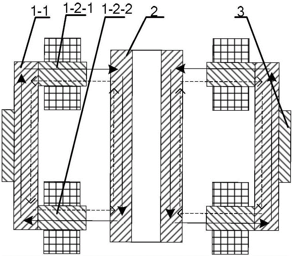
[0076] Such as figure 2 As shown, the stator 1 in this embodiment includes two axially placed armature teeth 1-2 and a stator core 1-1, and the stator core 1-1 and two armature teeth 1-2 form an "arcuate" structure .
[0077] Working principle: The bias flux and control flux generated by the radial force control winding pass through the stator core 1-1 and the upper armature teeth 1-2-1, and then radially flow through the radial air gap of the active bearing. Then it flows axially downward through the rotor iron core 2, then ra...
Embodiment 2
[0080] Embodiment 2: In this embodiment, the large-gap radial magnetic bearing of the segmented stator includes four stators 1 and rotor cores 2; the four stators 1 are evenly distributed around the rotor core 2 along the circumferential direction, and the four stators 1 There is no closed magnetic circuit between them; there is a radial air gap between each stator 1 and the rotor core 2, and a closed magnetic circuit is formed.
[0081] Such as image 3 As shown, the stator 1 in this embodiment includes three axially placed armature teeth 1-2 and a stator core 1-1, and the stator core 1-1 and three armature teeth 1-2 form a "bow" structure .
[0082] Working principle: The radial force of the upper armature tooth 1-2-1 controls the bias magnetic flux and control magnetic flux generated by the winding, passes through the stator core 1-1 downward, and then flows to the middle armature tooth 1-2- 3. Then flow radially through the radial air gap of the active bearing, then flow...
Embodiment 3
[0086] Embodiment 3: as Figure 4 As shown, the large-gap radial magnetic bearing of the divided stator in this embodiment includes three stators 1 and rotor cores 2; the three stators 1 are evenly distributed around the rotor core 2 along the circumferential direction, and the three stators 1 There is no closed magnetic circuit between them; there is a radial air gap between each stator 1 and the rotor core 2, and a closed magnetic circuit is formed.
[0087] The structure of the stator 1 is the same as that of the first embodiment.
PUM
 Abstract
Description
Claims
Application Information
 - R&D
- Intellectual Property
- Life Sciences
- Materials
- Tech Scout
- Unparalleled Data Quality
- Higher Quality Content
- 60% Fewer Hallucinations
Browse by: Latest US Patents, China's latest patents, Technical Efficacy Thesaurus, Application Domain, Technology Topic, Popular Technical Reports.
© 2025 PatSnap. All rights reserved.Legal|Privacy policy|Modern Slavery Act Transparency Statement|Sitemap|About US| Contact US: help@patsnap.com