Steel rail automatic detection device and method

An automatic detection device and rail technology, which is applied to measurement devices, optical devices, optical testing of flaws/defects, etc., can solve problems such as long use time error, measurement result error, wear of fixed and movable probes, etc. , the effect of small error

Inactive Publication Date: 2017-02-22
WUHAN HANNING TECH
View PDF7 Cites 13 Cited by
  • Summary
  • Abstract
  • Description
  • Claims
  • Application Information

AI Technical Summary

Problems solved by technology

[0003] In the prior art, the detection of the geometric dimensions and appearance quality of the rails is mostly mechanical contact measurement, which needs to be measured in direct contact with the rails. During the long-term measurement process, the fixed and movable probes will be worn, which will cause the measurement results to exist. Error, and the longer the use time, the larger the error will be

Method used


Image

  • Steel rail automatic detection device and method
  • Steel rail automatic detection device and method
  • Steel rail automatic detection device and method

Examples


Embodiment Construction

[0060] In order to make the purpose, technical solutions and advantages of the embodiments of the present invention clearer, the technical solutions in the embodiments of the present invention will be clearly and completely described below in conjunction with the drawings in the embodiments of the present invention. Obviously, the described embodiments are only It is a part of embodiments of the present invention, but not all embodiments. The components of the embodiments of the invention generally described and illustrated in the figures herein may be arranged and designed in a variety of different configurations. Accordingly, the following detailed description of the embodiments of the invention provided in the accompanying drawings is not intended to limit the scope of the claimed invention, but merely represents selected embodiments of the invention. Based on the embodiments of the present invention, all other embodiments obtained by those skilled in the art without making...


PUM


Abstract

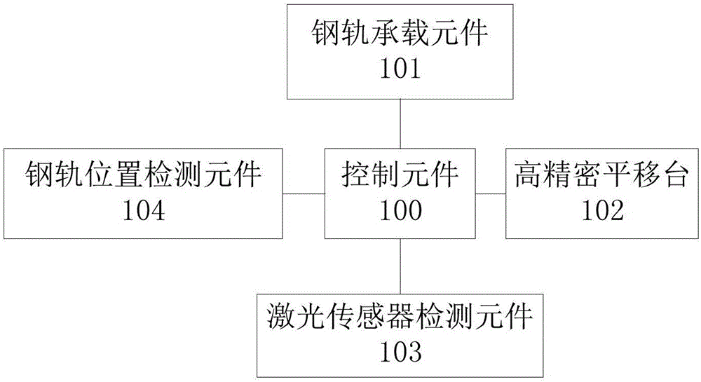
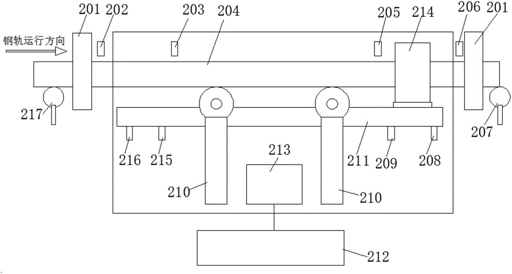
The invention provides a steel rail automatic detection device and method. The device comprises a steel rail carrying element, a steel rail position detecting element, a laser sensor detecting element, a high precision translation table and a control element, the steel rail carrying element, the steel rail position detecting element, the laser sensor detecting element, and the high precision translation table are connected with the control element, the laser sensor detecting element is arranged on the high precision translation table, the high precision translation table is used to drive the laser sensor detecting element to move, the steel rail carrying element comprises a retractable rail carrying table, the retractable rail carrying table is in a falling state when the retractable rail carrying table is in operation and is in a lifting state when the retractable rail carrying table is not in operation, the steel rail carrying element is used to carry short steel rails and prevents the short steel rails from falling from the downward line. The steel rail automatic detection device adopts the laser sensor detecting element to realize the non-contact detection of the steel rails, is free of detection probe wearing, and has the positive effects of high detection precision and small error.

Description

technical field [0001] The invention relates to the technical field of rail detection, in particular to a rail automatic detection device and method. Background technique [0002] At present, the current high-speed railways have adopted the track laying form of seamless rails. In the welding operation of seamless rails, the appearance quality and geometric dimensions of the rails, especially the rail top width, rail bottom width, rail height, and straightness Parameters such as torsion and distortion are important factors affecting the straightness of the welded rail; the appearance geometry of the rail before welding will directly affect the quality of the welded rail, and then affect the straightness of the seamless track after laying, so for The control of the appearance geometric dimension of the rail before welding is very important to improve the quality of the seamless rail. [0003] In the prior art, the detection of the geometric dimensions and appearance quality o...

Claims


Application Information

Patent Timeline
Patent Type & Authority Applications(China)
IPC IPC(8): G01B11/00G01B11/24G01N21/89
CPCG01B11/00G01B11/24G01N21/8914G01N2021/8918
Inventor 毛庆洲郑继忠李志明毛庆乐
Owner WUHAN HANNING TECH
Why Eureka
Try Eureka