Exhaust apparatus for exhaust simulation test of exhaust nozzle of supersonic engine

A technology of exhaust device and simulation test, which is applied in the direction of engine test, measurement device, internal combustion engine test, etc. It can solve the problems of huge structure, low efficiency, and inability to meet the requirements of various engine tests.

Active Publication Date: 2017-02-22
BEIJING AEROSPACE SANFA HIGH TECH
View PDF7 Cites 18 Cited by
  • Summary
  • Abstract
  • Description
  • Claims
  • Application Information

AI Technical Summary

Problems solved by technology

[0002] When simulating the high-altitude flight state of a supersonic engine on the ground, the engine is usually installed in the high-altitude simulation cabin first, and the high-altitude cabin is pumped with air extraction equipment so that the pressure in the high-altitude simulation cabin is the same as the environment where the engine is flying at high altitude. The pressure is the same, and then the engine is ignited, and the high-altitude flight simulation test is carried out. During the test, the pressure in the high-altitude simulation cabin must always be kept the same as the ambient pressure at the altitude of the engine when it is flying at high altitude. The gas is discharged from the high-altitude simulation cabin. In the prior art, an ejector or a vacuum tank is usually used for pumping air, and the pressure outside the high-altitude simulation cabin is usually 0.11MPa, while the ambient pressure at the flying height of the supersonic engine is only about 100% of the atmospheric pressure. 0.1 times, or even 0.01 times, the boost ratio of the exhaust system should reach 10 to 100, and the flow rate of the corresponding exhaust system inlet is as high as ten kilograms or even hundreds of kilograms per second. The flow rate depends only on the pressurization of the ejector, and three to four stages must be connected in series. If a vacuum tank is used, the volume of the vacuum tank must be as high as tens of thousands of cubic meters. It can be seen that no matter whether the ejector or the vacuum tank is used alone as the pumping Air equipment requires a huge structure, which is not only inefficient, but also very expensive; secondly, the engine test bench usually needs to perform high-altitude flight simulation for various engines, and different engines, engine size, engine tail nozzle size, engine The outlet flows are all different, and a set of air extraction equipment cannot meet the test requirements of various engines; No pressure) of the ejected airflow, the device that completes the ejected airflow and sucks the ejected airflow for mixing injection or delivery. Since the ejector has no moving parts, it is reliable and widely used in the exhaust system of the engine test bench; and The geometrical and positional relationship of the ejector that provides the ejector airflow and the blender of the blender is the key factor that determines the performance of the ejector. In the prior art, for the ejector of the exhaust system of the engine test bench, A mature and reasonable geometric and positional relationship between the ejecting part and the mixing part has not been formed, resulting in low ejecting performance of the ejector, reducing the efficiency of the test, and increasing the cost of the test; in addition, the high-altitude flight The gas discharged from the engine is a high-temperature gas, and its temperature is usually above 350°C. When the high-temperature gas discharged from the engine flows inside the metal pipe, due to the property of metal thermal expansion and contraction, the pipe will expand axially. When the high-temperature medium flows Afterwards, as the metal pipe returns to normal temperature, the metal pipe will be shortened to its original length. The existing pipe support cannot absorb the axial length change of the metal pipe due to thermal expansion and contraction, which will cause the pipe support to deform or even break. The fixed connection of the high-altitude simulation cabin will also be deformed or even broken

Method used


Image

  • Exhaust apparatus for exhaust simulation test of exhaust nozzle of supersonic engine
  • Exhaust apparatus for exhaust simulation test of exhaust nozzle of supersonic engine
  • Exhaust apparatus for exhaust simulation test of exhaust nozzle of supersonic engine

Examples


Embodiment Construction

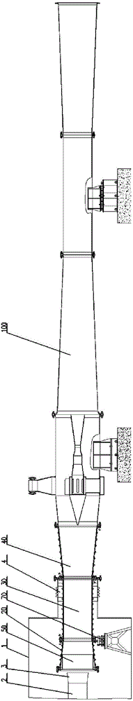
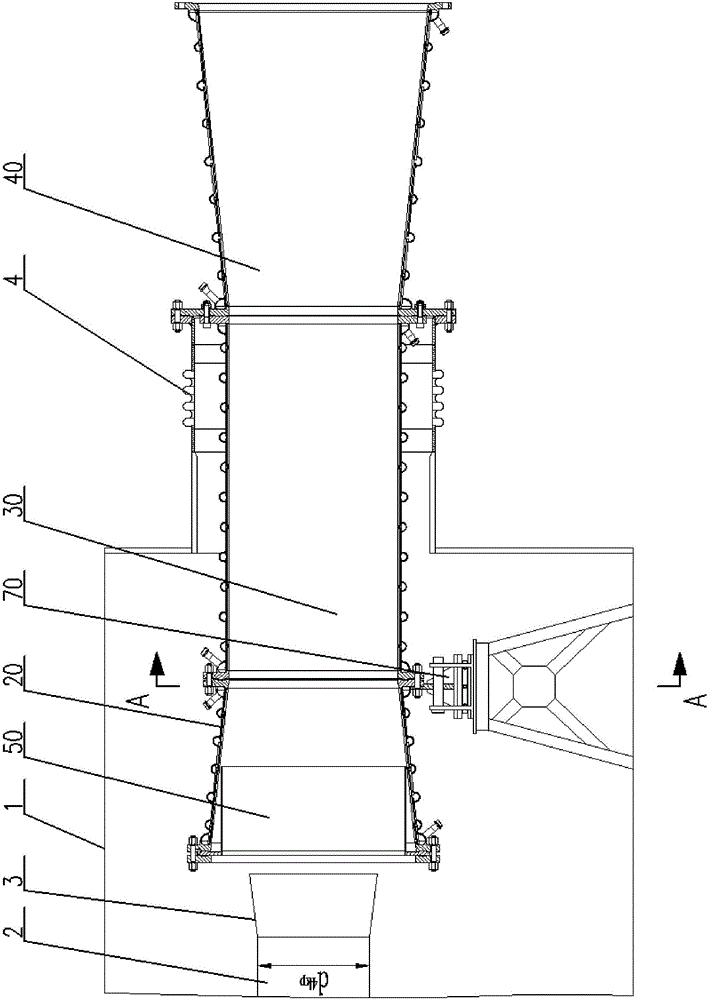
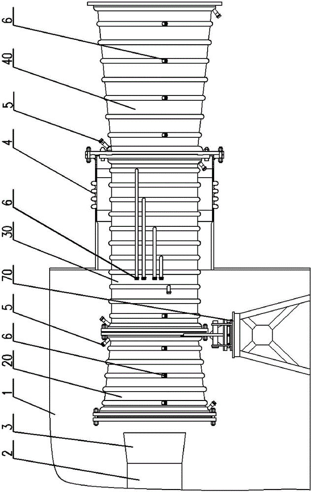
[0095] see Figure 1-25, an exhaust device for a supersonic engine tail nozzle exhaust simulation test, according to the flow direction of the exhaust gas at the outlet of the engine tail nozzle 3, the exhaust device includes a coaxial tail chamber and an ejector 100 that are fixedly connected in sequence, The tail chamber includes a fixed large tail chamber and a replaceable small tail chamber 50. According to the flow direction of the exhaust gas at the outlet of the engine tail nozzle 3, the fixed large tail chamber includes a tail chamber converging section 20 that is coaxially connected sequentially through flanges, The straight section 30 of the tail chamber and the expansion section 40 of the tail chamber, the replaceable small tail chamber 50 includes a small tail chamber flange 52 and a small tail chamber cylinder 51 that are coaxially fixedly connected, and the small tail chamber cylinder 51 is connected to the tail chamber The converging section 20 is coaxially arra...


PUM


Abstract

The invention discloses an exhaust apparatus for an exhaust simulation test of an exhaust nozzle of a supersonic engine. The exhaust apparatus comprises a tail chamber and an ejector, the tail chamber comprises a fixed large tail chamber and a replaceable small tail chamber, the fixed large tail chamber comprises a tail chamber convergence segment, a tail chamber equal-diameter segment, and a tail chamber expansion segment, the replaceable small tail chamber comprises a small tail chamber flange and a small tail chamber cylinder body, the small tail chamber cylinder body is arranged in the tail chamber convergence segment, the fixed large tail chamber is provided with a circulating cooling water device and a cooling water spraying device, the ejector comprises a low-pressure chamber, a transition segment, a blending convergence segment, a blending equal-diameter segment and a blending expansion segment, the inner part of the low-pressure chamber is fixedly connected with a circular ring diversion and guiding device, an ejection airflow conveying pipeline, an ejection airflow convergence segment and an ejection airflow expansion segment, and cross sections of an outlet of the low-pressure chamber and an outlet of the ejection airflow expansion segment are located in the same vertical plane. According to the exhaust apparatus, test requirements for simulating high-altitude flight states of different supersonic engines on the ground can be met.

Description

technical field [0001] The invention relates to an exhaust device, in particular to an exhaust device for a supersonic engine tail nozzle exhaust simulation test. Background technique [0002] When simulating the high-altitude flight state of a supersonic engine on the ground, the engine is usually installed in the high-altitude simulation cabin first, and the high-altitude cabin is pumped with air extraction equipment so that the pressure in the high-altitude simulation cabin is the same as the environment where the engine is flying at high altitude. The pressure is the same, and then the engine is ignited, and the high-altitude flight simulation test is carried out. During the test, the pressure in the high-altitude simulation cabin must always be kept the same as the ambient pressure at the altitude of the engine when it is flying at high altitude. The gas is discharged from the high-altitude simulation cabin. In the prior art, an ejector or a vacuum tank is usually used ...

Claims


Application Information

Patent Timeline
Patent Type & Authority Applications(China)
IPC IPC(8): G01M15/10G01M13/00
CPCG01M13/00G01M15/106
Inventor 周培好赵聚均王文彬孙建
Owner BEIJING AEROSPACE SANFA HIGH TECH
Why Eureka
Try Eureka