Lamp bar fixed structure, backlight module and displayer

A technology for fixing structures and light strips, which is applied in the directions of instruments, optics, nonlinear optics, etc., can solve the problems of increased cost and cumbersome assembly, and achieve the effects of easy disassembly, simplified assembly process, and avoid damage

Inactive Publication Date: 2017-02-22
GUANGDONG CHANGHONG ELECTRONICS
View PDF5 Cites 6 Cited by
  • Summary
  • Abstract
  • Description
  • Claims
  • Application Information

AI Technical Summary

Problems solved by technology

[0007] In view of the above-mentioned deficiencies in the prior art, the present invention provides a light bar fixing structure, a backlight module and a display, aiming at solving the problems of increased cost and cumbersome assembly due to the use of other auxiliary materials in the light bar fixing method, and simplifying the fixing of the light bar on the backlight. board assembly process, saving man-hours and reducing the cost of the backlight module

Method used


Image

  • Lamp bar fixed structure, backlight module and displayer
  • Lamp bar fixed structure, backlight module and displayer
  • Lamp bar fixed structure, backlight module and displayer

Examples


Embodiment 1

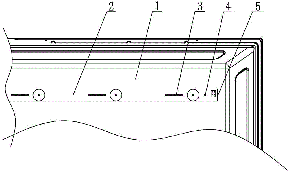
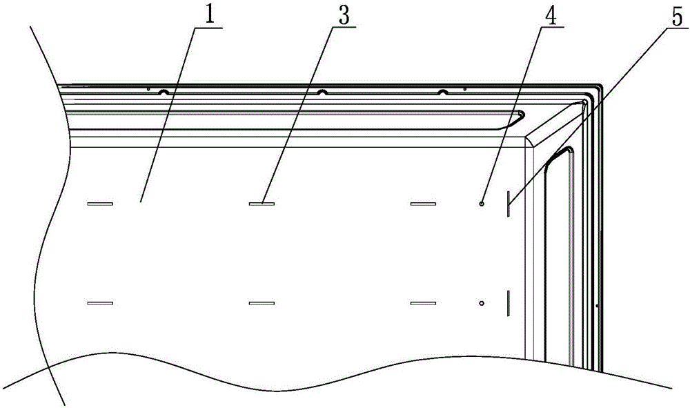
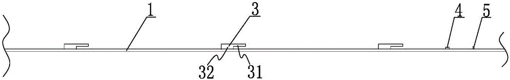
[0033] Please refer to the attached figure 1 to attach Figure 4 , a light bar fixing structure, used for positioning and fixing the light bar 2 and the back plate 1, including the light bar 2 and the back plate 1, wherein:

[0034] Several pre-positioning holes 21 and at least one position-limiting positioning hole 22 are provided on the light bar. In this embodiment, the pre-positioning holes are horizontally arranged on the light bar, and two limit positioning holes are provided, which are respectively symmetrically distributed on the side near the end of the light bar at both ends.

[0035] The back plate can be made of metal, and there are several hanging lugs 3 corresponding to the pre-positioning holes one by one and at least one positioning post 4 cooperating and fixedly connecting with the limiting positioning holes 22 protruding from the back plate. In this embodiment, the hanging ear 3 includes a connecting part 32 and a pressing part 31, the connecting part 32 pr...

Embodiment 2

[0044] The only difference between this implementation and Embodiment 1 is the structure of the limit stopper. The limit stopper in this embodiment is replaced by a blocking strip longitudinally arranged on the back plate, which is used to limit the end of the light bar. The bottom can also prevent the light bar from slipping out, and the structure is simple. The features of other components of this embodiment are the same as those of Embodiment 1, and will not be repeated here.


PUM


Abstract

The invention provides a lamp bar fixed structure, backlight module and displayer to position with a backboard and fix for a lamp bar, which includes the lamp bar and the backboard. The lamp bar is provided with several pre-determined bit holes and at least a spacing location hole. The backboard is convexly provided with several hangers to connect with corresponding pre-determined bit holes and at least a locating dowel is fixedly connected with the spacing location hole. The size of hangers is smaller than that of pre-determined bit holes. Hangers include: a connecting portion protrudes from the backboard, a nip portion is located at the top of the connecting portion, and the gap is formed between the backboard upper surface. The lamp bar is sleeved into hangers by pre-determined bit holes and the lamp bar is snapped in the gap so as to closely contact with the backboard. The lamp bar fixed structure, backlight module and displayer fix the lamp bar on the backboard without supplies such as screw or double faced adhesive tapes and solve problems of assembling the lamp bar with trivial details. The lamp bar fixed structure, backlight module and displayer also have the advantage of simplifying assembling procedure, saving man-hour and reducing the cost of backlight module.

Description

[0001] Technical field: [0002] The invention relates to the technical field of liquid crystal display devices, in particular to a light bar fixing structure, a backlight module and a display. [0003] Background technique: [0004] In a traditional backlight module, the light bar and the backplane are generally connected by screws or double-sided adhesive. Among them, when the fixing method of screw connection is used, manual locking is usually required, and the number of screws is large, the cost of manpower and materials is high, and the positioning of the fixed front light bar is difficult, and it is difficult to disassemble after an abnormal deviation occurs, which consumes a lot of man-hours; When the double-sided adhesive is used for fixing, the light bar needs to be completely pasted on the back panel, which is troublesome to rework, and the scrap rate is high when there is residual glue. After adding double-sided tape between the back panel and the light bar, it will...

Claims


Application Information

Patent Timeline
Patent Type & Authority Applications(China)
IPC IPC(8): G02F1/13357
CPCG02F1/133608
Inventor 蒋吉强杨奇唐德良姚昭罗兵安亚斌罗国威李志李平
Owner GUANGDONG CHANGHONG ELECTRONICS
Why Eureka
Try Eureka