Temperature Control System and Optical Console

A technology of temperature control system and temperature controller, which is applied in the direction of temperature control using digital devices, temperature control using electric methods, refrigeration and liquefaction, etc. It can solve the problems of long test period, heavy test work, slow temperature change of temperature control system, etc. problem, to achieve the effect of saving test time, good effect and increasing temperature change rate

Inactive Publication Date: 2018-06-22
EAST CHINA NORMAL UNIV
View PDF6 Cites 0 Cited by
  • Summary
  • Abstract
  • Description
  • Claims
  • Application Information

AI Technical Summary

Problems solved by technology

The result of changing and combining various parameters is a wide variety of samples to be tested, and the existing temperature control system changes slowly (the test cycle is long), which ultimately leads to extremely heavy testing work

Method used


Image

  • Temperature Control System and Optical Console
  • Temperature Control System and Optical Console
  • Temperature Control System and Optical Console

Examples


Embodiment 1

[0063] The structure of the temperature control system of the present embodiment is as follows:

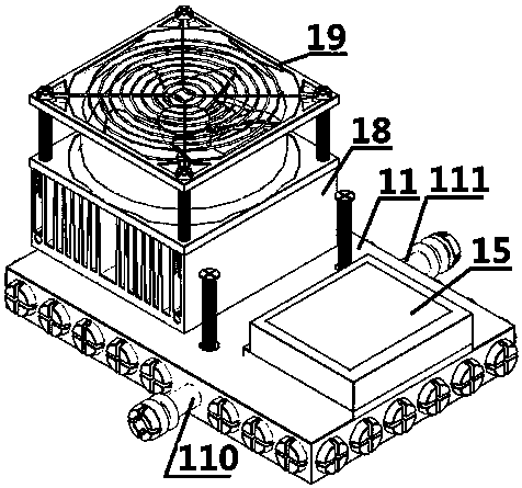
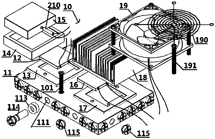
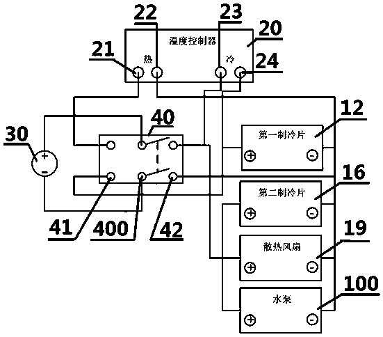
[0064] Please combine Figure 1-3 It should be understood that the temperature control system of this embodiment includes a refrigeration unit 10, a temperature controller 20 and a switching power supply 30, the temperature controller 20 can control the switching power supply 30 to drive the refrigeration unit 10 to cool or heat,

[0065] The refrigeration unit 10 includes a copper heat dissipation support plate 11, a first refrigeration sheet 12, a first heat insulation pad 13, an annular heat insulation sheet 14, a temperature control copper block 15, a second refrigeration sheet 16, and a second heat insulation pad 17. Radiating block 18,

[0066] The heating surface and the cooling surface of the first refrigerating sheet 12 are respectively in thermal contact with the copper heat dissipation support plate 11 and the temperature control copper block 15 respectively, and the f...

Embodiment 2

[0080] The structure of the temperature control system of the present embodiment is as follows:

[0081] The temperature control system of this embodiment has many similarities with the temperature control system of Embodiment 1, and these similarities will not be repeated. It is different from the temperature control system of Embodiment 1. Please combine Image 6 It should be understood that the circuit elements of the switching power supply 30 and the circuit elements of the temperature controller 20 are integrated on the same PCB board, and the switching power supply 30 includes a transformer unit T1, a rectifier unit D1~D4, and a filter unit electrically connected in sequence C1 and a voltage stabilizing unit IC1; the temperature controller 20 includes a wireless transceiver unit W1, a temperature acquisition unit U1, a signal processing unit IC2 and an H-bridge circuit with enabling control and direction logic, and the H-bridge circuit has An enabling terminal ENABLE, a ...


PUM


Abstract

The invention provides a temperature control system and an optical console having the same temperature control system. The temperature control system comprises a refrigeration unit, a temperature controller and a switching power supply. The temperature controller controls the switching power supply to drive the refrigeration unit to carry out refrigeration or heating. The refrigeration unit comprises a copper heat radiation support plate, a first refrigeration sheet, a first heat insulation pad, an annular heat spacer, a temperature control copper block, a second refrigeration sheet, a second heat insulation pad and a heat radiation block. The two refrigeration sheets and the copper heat radiation support plate are used to cooperatively buffer temperature control, the conventional technical problem that the accumulated heat is high and the refrigeration is hard is solved, the temperature changing rate is greatly improved, the testing time is saved, the usage is convenient, and the low temperature refrigeration effect is good.

Description

technical field [0001] The invention relates to the field of semiconductor temperature control, in particular to a temperature control system and an optical console containing it. Background technique [0002] In the experimental testing stage of scientific research institutes and universities, it is often necessary to control the temperature of semiconductor devices (such as lasers and solar cells) in order to test their photoelectric characteristics under constant or variable temperature conditions, and then develop targeted improvements. [0003] Due to the development and improvement stage, in order to obtain better device performance, it is usually necessary to carefully change the composition of the combined material, temperature, humidity and pressure parameters. The result of changing and combining various parameters is a wide variety of samples to be tested. Moreover, the existing temperature control system changes temperature slowly (longer test cycle), which ultim...

Claims


Application Information

Patent Timeline
Patent Type & Authority Patents(China)
IPC IPC(8): G05D23/19F25B21/02
CPCF25B21/02F25B2321/021F25B2321/0251G05D23/1917Y02B30/70
Inventor 马传贺陈晔安雪娥王宇
Owner EAST CHINA NORMAL UNIV
Why Eureka
Try Eureka