Circular polarization microstrip antenna

A microstrip antenna, circularly polarized technology, applied in antennas, resonant antennas, electrical short antennas and other directions, can solve the problems of difficult structure, low gain, complex structure and so on

Pending Publication Date: 2017-02-22
CHONGQING UNIV +1
View PDF11 Cites 6 Cited by
  • Summary
  • Abstract
  • Description
  • Claims
  • Application Information

AI Technical Summary

Problems solved by technology

However, the axial ratio bandwidth of the traditional microstrip antenna is usually about 1%. In the prior art, there are mainly methods to expand the axial ratio bandwidth of the antenna: one is to use coupling feeding, coplanar waveguide feeding, and L-shaped probe feeding. and other methods can increase the axial ratio bandwidth to about 30%, but the general gain is low and its structure is not easy to process and manufacture; the second is to increase the parasitic patch above the radiation patch, and use the multi-resonance principle to increase the impedance bandwidth and axial ratio bandwidth. However, the overall section height of the antenna has increased; the third is to add a variety of perturbation structures on the radiation patch, and form multiple current paths on the surface of the patch to increase the bandwidth. This method has a complex structure and a high degree of design freedom.

Method used


Image

  • Circular polarization microstrip antenna
  • Circular polarization microstrip antenna
  • Circular polarization microstrip antenna

Examples


Embodiment Construction

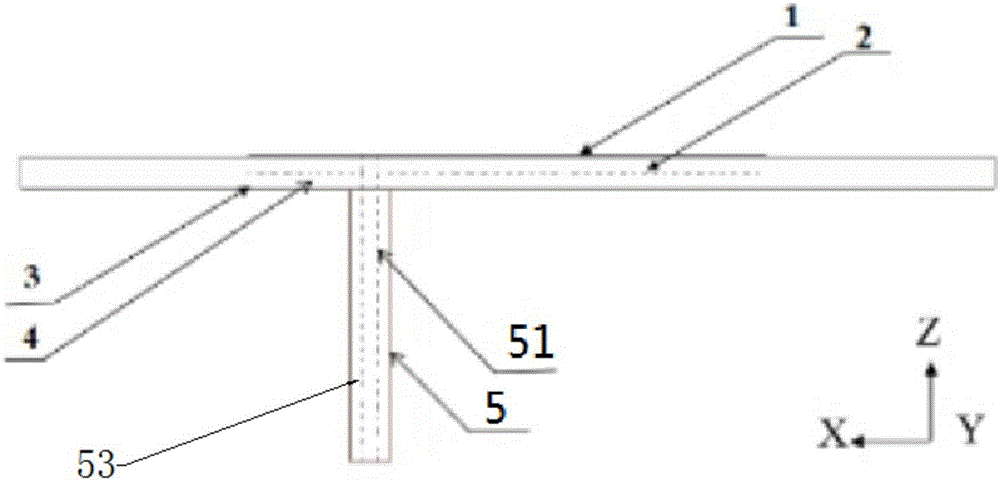
[0025] Specific embodiments of the present invention will be described in detail below in conjunction with the accompanying drawings. It should be understood that the specific embodiments described here are only used to illustrate and explain the present invention, and are not intended to limit the present invention. In the present invention, in the case of no contrary description, the used orientation words such as "width direction, length direction, thickness direction" usually refer to the "X axis, Y axis, Z axis" in the coordinate axes of the corresponding drawings. pointing direction.

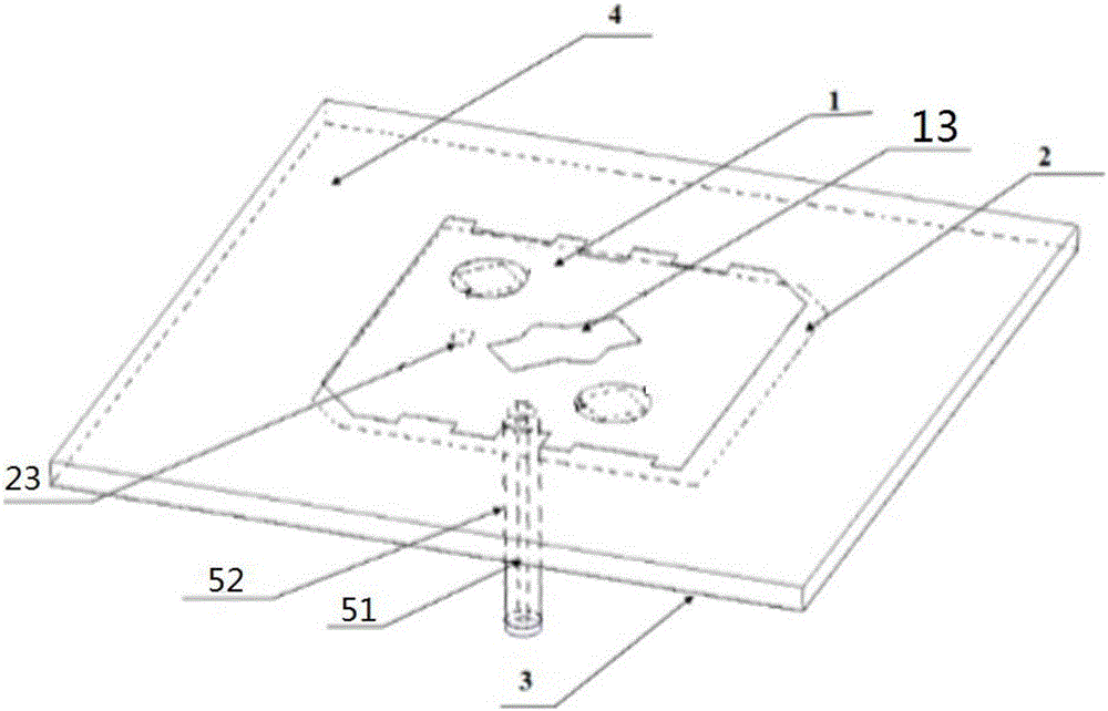
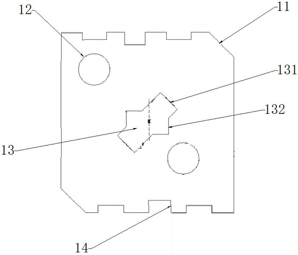
[0026] Such as figure 1 and figure 2 As shown, the present invention provides a circularly polarized microstrip antenna, including a dielectric substrate 4, a first radiation patch 1, a second radiation patch 2, a ground plate 3 and a coaxial cable 5, wherein the dielectric substrate 4 forms There are opposite first and second surfaces, the first radiating patch 1 is attached to the fi...


PUM


Abstract

The invention discloses a circular polarization microstrip antenna. The circular polarization microstrip antenna comprises a medium substrate, a first radiation paster, a second radiation paster, a grounding board and a coaxial cable, wherein the medium substrate comprises a first surface and a second surface which are opposite to the first surface, the first radiation paster is attached to the first surface of the medium substrate, the second radiation paster is embedded in the medium substrate and is in parallel with the first radiation paster, the grounding board is attached to the second surface of the medium substrate, and the coaxial cable penetrates through the medium substrate and the second radiation paster to connect with the first radiation paster. According to the circular polarization microstrip antenna, the two radiation pasters and near-field coupling between the two radiation pasters are utilized to expand axial ratio bandwidth of the antenna on the condition that antenna profile height does not increase, the circular polarization microstrip antenna in relatively wide frequency band scope can generate a axial ratio curve having three resonance peaks, circular polarized wave turning directions are consistent, compared with an antenna with same profile height, axial ratio bandwidth of the circular polarization microstrip antenna is improved to a wider mode.

Description

technical field [0001] The present invention relates to the technical field of antennas, in particular to a circularly polarized microstrip antenna. Background technique [0002] Circularly polarized microstrip antennas have the characteristics of anti-fading and anti-rain and fog interference, and can accept incoming waves in any direction and polarization. Circularly polarized microstrip antennas mainly use single-feed method for feeding. Such as vehicle equipment, WeChat communication and other directions. However, the axial ratio bandwidth of the traditional microstrip antenna is usually about 1%. In the prior art, there are mainly methods to expand the axial ratio bandwidth of the antenna: one is to use coupling feeding, coplanar waveguide feeding, and L-shaped probe feeding. and other methods can increase the axial ratio bandwidth to about 30%, but the general gain is low and its structure is not easy to process and manufacture; the second is to increase the parasitic...

Claims


Application Information

Patent Timeline
Patent Type & Authority Applications(China)
IPC IPC(8): H01Q9/04H01Q1/36H01Q1/48H01Q1/50
CPCH01Q1/36H01Q1/48H01Q1/50H01Q9/0428
Inventor 唐明春陈晓明刘书君李梅曾孝平
Owner CHONGQING UNIV
Why Eureka
Try Eureka