Electrical connector

A technology for electrical connectors and contact sections, which is applied in the field of multiple injection-molded electrical connectors, can solve the problems of small spacing and difficult positioning of sealing glue, and achieve the effects of easy sealing, stable overall structure, and prevention of injection molding burrs

Active Publication Date: 2017-02-22
KUNSHAN JIAHUA ELECTRONICS
View PDF6 Cites 12 Cited by
  • Summary
  • Abstract
  • Description
  • Claims
  • Application Information

AI Technical Summary

Problems solved by technology

[0004] However, the existing USB Type-C receptacle electrical connector has a large number of terminals, a small spacing between the terminals, mirror symmetry between the upper and lower rows of terminals, and the ideal overall shape and size. Therefore, during the injection molding process, each The sealing and positioning of the module becomes difficult, especially in the position where the solder pins at the rear end of the socket electrical connector are densely packed

Method used


Image

  • Electrical connector
  • Electrical connector
  • Electrical connector

Examples


Embodiment Construction

[0034] In order to make the purpose, technical solutions and advantages of the present invention clearer, the present invention will be described in detail below in conjunction with the accompanying drawings and specific embodiments, and for the convenience and accuracy of expression, all references to directions in this paper should be referred to figure 1 , the butt end of the docking electrical connector (docking plug, not shown) is the front end, and the other end is the rear end.

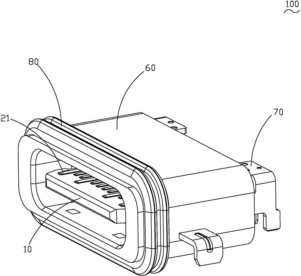
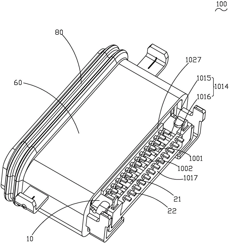
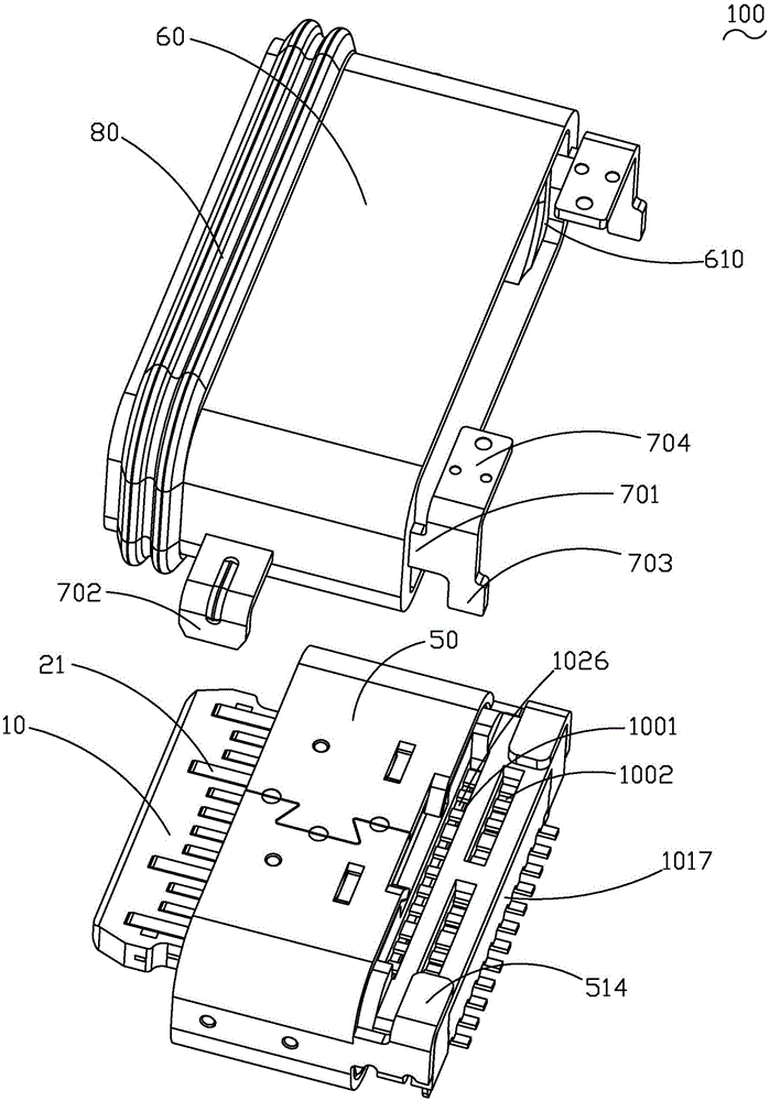
[0035] see Figure 1 to Figure 16 As shown, the electrical connector 100 disclosed in the present invention can be sunk mounted on a mating circuit board (not shown) and can be mated with the mating electrical connector. The electrical connector 100 includes an insulating body 10, an upper row terminal group 21 and a lower row terminal group 22 embedded in the insulating body 10, a shielding plate 30 embedded in the insulating body 10 and fixed on the insulating body 10. The metal piece 40 and...


PUM


Abstract

The utility model relates to an electric connector, comprising an insulating body, upper and lower terminal sets composed by a plurality of terminals which are fixed on the insulating body, shielding plate fixed in the insulating body and metal casing fixed outside the insulating body. The insulating body comprises an inner insulator and an outer insulator. The upper and lower terminal sets and the shielding plate fixed to the inner insulator. The formation of upper outer appearance and lower outer appearance on the proper position under the external insulator is for the mold sealing glue when injection molding outside insulator appeared. In order to reduce the influence of mold insert on the terminal. At the same time, it can prevent the generation of injection burring. In addition, the utility model has the advantages of stable structure, good overall strength, simple manufacturing process, easy sealing of multiple injection molding and etc.

Description

technical field [0001] The invention relates to an electrical connector, in particular to an electrical connector with multiple injection molding. Background technique [0002] In the past, the Universal Serial Bus (USB) was used by the general public, and developed from the USB2.0 transmission specification to the current USB3.0 transmission specification with a faster transmission speed. [0003] However, the appearance, structure, terminal contact method, number of terminals, distance between terminals (Pitch) and pin assignment (Pin Assignment) of the latest generation of USB Type-C electrical connectors are completely different from the current USB electrical connectors. different. The USB Type-C socket electrical connector includes two rows of flat terminals arranged on the rubber core, and the rubber core is covered with an outer iron shell and other structures. Generally, the plastic core of the USB Type-C socket electrical connector is formed by assembling and inj...

Claims


Application Information

Patent Timeline
Patent Type & Authority Applications(China)
IPC IPC(8): H01R13/504H01R13/46H01R12/71H01R31/06H01R13/52H01R13/6591
CPCH01R12/714H01R13/46H01R13/5045H01R13/5202H01R13/5219H01R13/6591H01R31/06
Inventor 段国强
Owner KUNSHAN JIAHUA ELECTRONICS
Why Eureka
Try Eureka