Structure of electric connector

A technology of electrical connectors and connectors, which is applied in the direction of connection, parts and circuits of connection devices, and can solve problems such as maintenance or installation troubles

Active Publication Date: 2017-02-22
王秋文
View PDF4 Cites 2 Cited by
  • Summary
  • Abstract
  • Description
  • Claims
  • Application Information

AI Technical Summary

Problems solved by technology

[0003] In the case of FPC connectors, they are usually only used for signal links between electronic devices. For external I/O connectors, they are relative

Method used


Image

  • Structure of electric connector
  • Structure of electric connector
  • Structure of electric connector

Examples


Embodiment Construction

[0045] In order to further explain the technical solution of the present invention, the present invention will be described in detail below through specific examples.

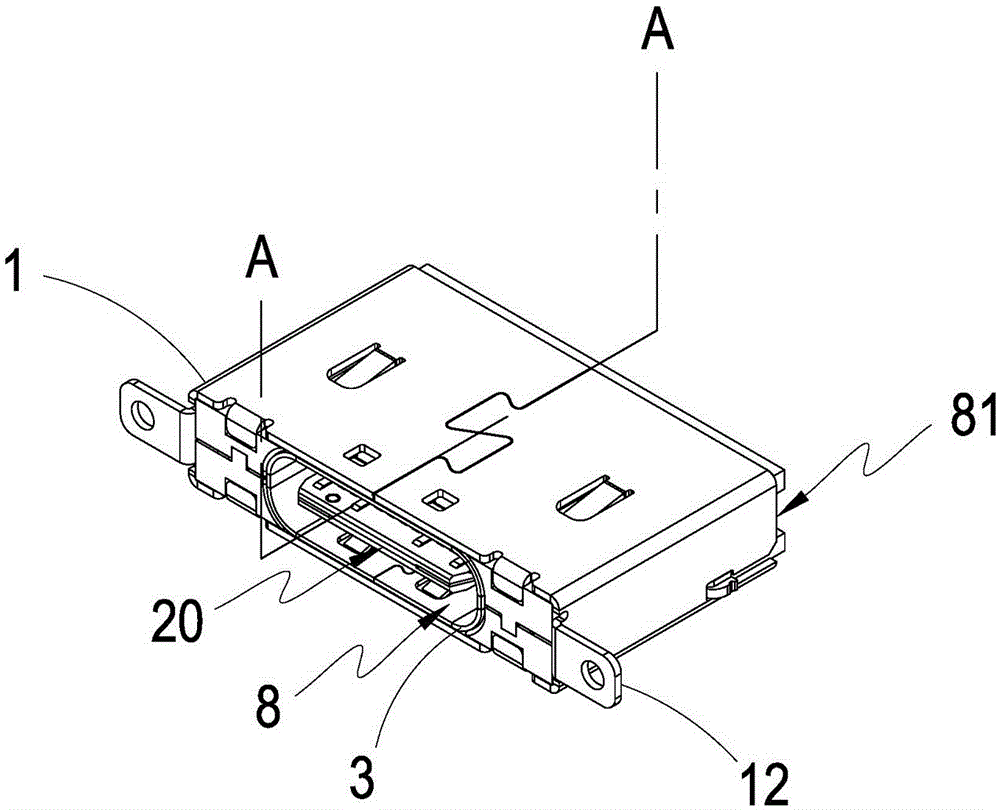
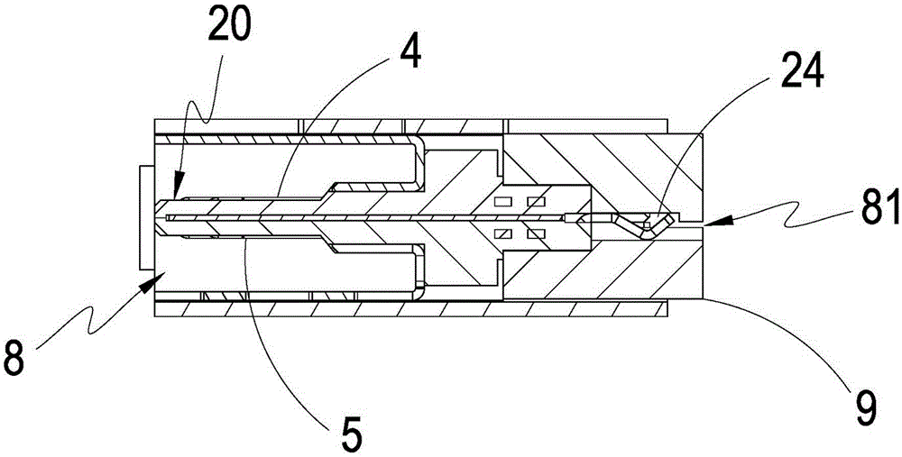
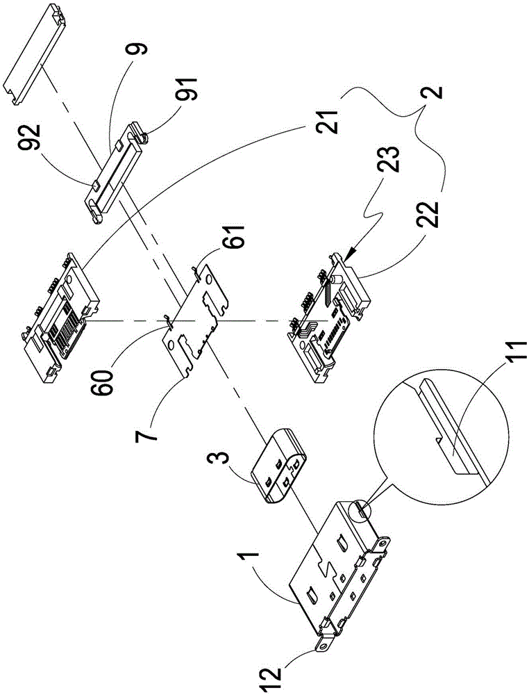
[0046] see Figure 1 to Figure 6 As shown, it can be clearly seen from the figure that the structure of the electrical connector of the present invention includes:

[0047] A shielding shell 1, which is respectively formed with a track 11 on both sides of the rear, and has a fixed buckle 12 on the left and right sides of the shielding shell 1 respectively;

[0048] At least one insulating colloid group 2 accommodated in the shielding shell 1, the insulating colloid group 2 also includes a first insulating colloid 21 and a second insulating colloid 22 arranged on one side of the first insulating colloid 21, and the first insulating colloid The insulating colloid 21 and the second insulating colloid 22 are combined to form a tongue part 20, and the insulating colloid group 2 forms a setting space 23 for an inner...


PUM


Abstract

The invention discloses a structure of an electric connector, and the structure mainly comprises a shielding housing, an insulating rubber group, first transmission conductor group front and back contact parts, second transmission conductor group front and back contact parts, a first plugging interface, and a second plugging interface. During the plugging of the connector, the connector can be plugged from the first plugging interface, and is electrically connected with the first and second transmission conductor group front contact parts, thereby achieving the movable plugging through the detachable lower insulating rubber while the forwarding and reverse plugging advantage is achieved (I/O connector interface), and enabling the first and second transmission conductor group rear contact parts to be connected with a flat cable in a plugging manner without welding. Moreover, a user enables the plugging to be more convenient through the elastic pushing parts at two sides of the detachable lower insulating rubber.

Description

technical field [0001] The invention relates to an electrical connector, in particular to a structure of an electrical connector that can quickly conduct electrical conduction with a flat cable without welding, and can be inserted into the front and back of the connector. Background technique [0002] At present, a variety of electronic devices have been developed to assist users in their use, and electronic devices include monitors, computers, cameras, plug-and-play devices (flash drives), etc. For the data or signal link, there must be a corresponding matching connector, and the connector types of various electronic devices are different, such as: USB series, SIM series, Micro SIM, etc., must use specific corresponding connectors. connectors to connect, so there will be multiple cables with different connectors. [0003] In the case of FPC connectors, they are usually only used for signal links between electronic devices. For external I / O connectors, they are relatively r...

Claims


Application Information

Patent Timeline
IPC IPC(8): H01R13/629H01R12/77H01R13/502
Inventor 王秋文
Owner 王秋文
Why Eureka
Try Eureka