Ureteral stent

A technology on ureters and stents, applied in the field of ureteral stents, can solve problems such as no longer, difficulty in urine to bladder flow, etc.

Active Publication Date: 2017-02-22
COLOPLAST AS
View PDF2 Cites 0 Cited by
  • Summary
  • Abstract
  • Description
  • Claims
  • Application Information

AI Technical Summary

Problems solved by technology

In this case, the flow of urine to the bladder may be difficult or may no longer be possible at all

Method used


Image

  • Ureteral stent
  • Ureteral stent
  • Ureteral stent

Examples


Embodiment approach

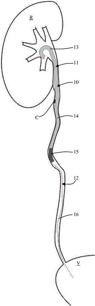
[0073] A. A ureteral stent comprising:

[0074]a body having a renal region configured for placement in a patient's kidney, a ureteral region connected to the renal region and configured for placement in a patient's ureter, and a proximal region In, the proximal region is connected to the ureter region and is located at the proximal end of the body; and

[0075] including the tail of the wire which is attached to the bracket; where

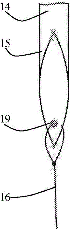
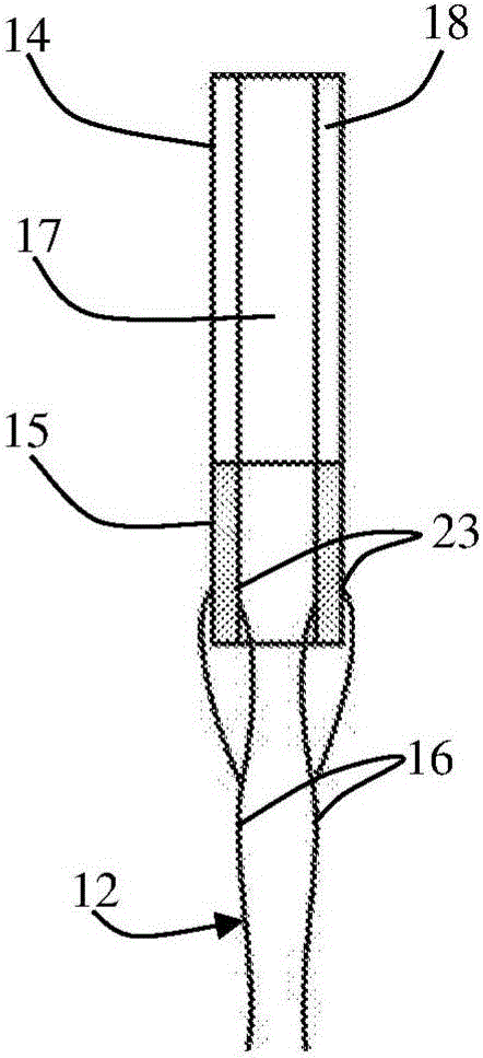
[0076] The proximal region is provided with a first flexibility greater than a second flexibility of the ureteral region of the stent, and in that the tail is rigidly connected to the ureteral region and extends beyond the proximal region.

[0077] B. The ureteral stent of embodiment A, wherein the ureteral region includes one or more through-openings, and the tail is secured to the body of the stent via one or more of the through-openings.

[0078] C. The ureteral stent of embodiment A or B, wherein the tail is secured to the body by a knot.

...


PUM


Abstract

The present invention relates to a ureteral stent (10) having a body (11) and a tail (12). The body (11) of the stent has a renal section (13) intended to be placed in a kidney (R) of a patient, a ureteral section (14) intended to be placed in at least part of a ureter of said patient, and a proximal section (15) arranged at a proximal end of the body of the stent. The tail (12) has at least one thread (16) intended to end in the bladder (V) of said patient. This stent is characterized in that said proximal section (15) has a flexibility greater than the flexibility of the ureteral a section (14) of the stent. The tail (12) is integral with said ureteral section and / or said proximal section (15) and extends beyond the proximal section (15).

Description

technical field [0001] The present invention relates to a ureteral stent intended to maintain the flow of urine between the kidney and bladder of a patient. Background technique [0002] In the human body, urine secreted by the kidneys passes through the ureters to the bladder and is then excreted from the body through the urethra during urination. In a healthy human body, urine is excreted in one direction from the kidneys to the bladder by the peristaltic motion of the ureters. [0003] Certain urinary tract disorders or certain diseases may prevent this voiding in the direction of the bladder. These conditions are especially likely due to the presence of stones or tumors or obstruction of the ureteropelvic junction. In such cases, the flow of urine to the bladder may be difficult or may no longer be possible at all. Urine retained in the kidneys swells and may cause renal colic. To relieve this condition, a stent may be placed in the ureter to restore the function of ...

Claims


Application Information

Patent Timeline
Patent Type & Authority Applications(China)
IPC IPC(8): A61M27/00
CPCA61M27/008A61M2210/1078A61M2210/1082A61F2250/0036A61F2250/0029A61F2/94A61F2002/048
Inventor S·塞吉T·贝伊维尔特J·米勒C·布格拉拉O·舒瓦舍
Owner COLOPLAST AS
Why Eureka
Try Eureka