Ultrasonic flow probe and method of monitoring fluid flow in a conduit

A fluid flow and ultrasonic technology, which is used in the field of ultrasonic flow probes for monitoring fluid flow in pipes such as exhaust pipes and monitoring fluid flow in pipes, which can solve the problems of low signal-to-noise ratio and poor ultrasonic signals.

Inactive Publication Date: 2017-02-22
POLLUTION CONTROL & MEASUREMENT EURO
View PDF7 Cites 1 Cited by
  • Summary
  • Abstract
  • Description
  • Claims
  • Application Information

AI Technical Summary

Problems solved by technology

However, pipes usually transmit a lot of noise. When the density of the fluid is very low, or the fluid is a gas, the ultrasonic signal transmitted by the pipe is very poor, resulting in a low signal-to-noise ratio
[0007] Additionally, the flow meters described above typically only measure the average velocity of fluid flow along the diameter of the pipe

Method used


Image

  • Ultrasonic flow probe and method of monitoring fluid flow in a conduit
  • Ultrasonic flow probe and method of monitoring fluid flow in a conduit
  • Ultrasonic flow probe and method of monitoring fluid flow in a conduit

Examples


Embodiment Construction

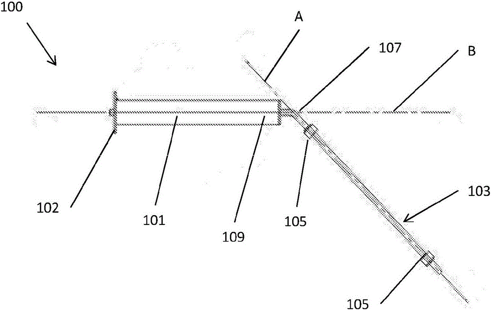
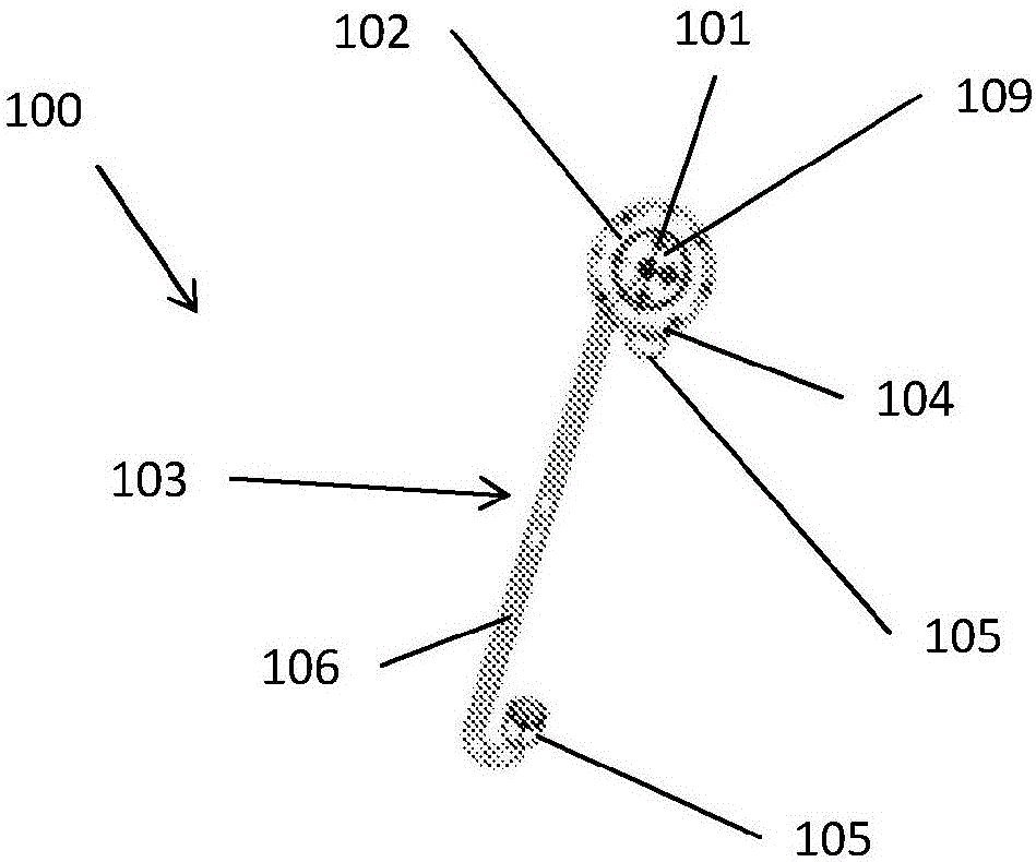
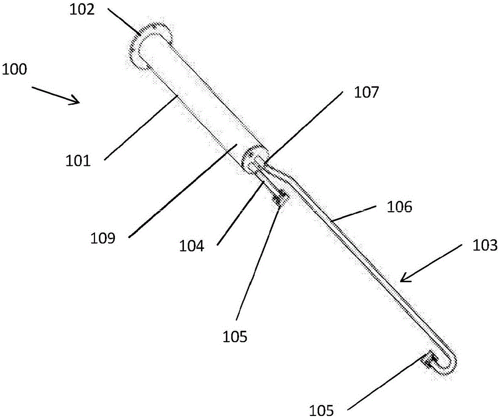
[0033] figure 1 , figure 2 and image 3 The ultrasonic flow probe 100 of the first embodiment is shown, which includes: a mounting part 101 , a bracket 103 mounted on the mounting part 101 , and two ultrasonic transducers 105 mounted on the bracket 103 .

[0034] The mounting part 101 is a cylindrical part. When the probe 100 is mounted on a surface, the mounting part extends away from the surface, and the axis of the cylinder is aligned along the mounting axis B. As shown in FIG. One end of the mounting member 101 is provided with a mounting plate 102 which is mounted on the surface on which the probe 100 is mounted. For example, mounting plate 102 may be affixed to or pass through the surface. In this embodiment, the mounting axis B is perpendicular to the mounting plate 102 due to the alignment of the mounting plate 102 with the surface.

[0035] The stand 103 includes two arms 104 , 106 . One end of each arm 104 , 106 is mounted to the free end of the mount 101 . An u...


PUM


Abstract

An ultrasonic flow probe (100) comprising a mounting member (101) for mounting on a surface of a conduit and thereby defining a mounting axis (B) perpendicular to the surface,a frame (103) mounted on the mounting member (101), and a plurality of ultrasonic transducers (105) mounted on the frame (103) and aligned along a primary axis (A); wherein the frame (103) and mounting member (101) are configurable such that the primary axis (A) is at an angle to the mounting axis (B) so that, in use, ultrasound passing between the transducers (105) travels at an angle to fluid flowing in the conduit.

Description

technical field [0001] The present invention relates to ultrasonic flow probes and methods for monitoring fluid flow in pipes, such as exhaust pipes. More particularly but not exclusively, the present invention relates to an ultrasonic flow probe for monitoring fluid flow in a pipeline. Background technique [0002] It is often desirable to understand the properties of fluid flow within a duct, such as an exhaust pipe. It may be due to regulatory requirements to monitor emissions, or a desire to improve the efficiency of industrial processes. Measured fluid flow characteristics may include: the average velocity of the fluid, the velocity profile of the fluid, and / or any excursions within the fluid from laminar flow. [0003] There are many techniques for measuring fluid flow, including optical, electrical, and ultrasonic methods. In a typical ultrasonic method, an ultrasonic probe transmits and receives ultrasonic waves along a path that has a component parallel to the fl...

Claims


Application Information

Patent Timeline
Patent Type & Authority Applications(China)
IPC IPC(8): G01F1/66
CPCG01F1/662G01F1/667G01P5/245
Inventor 罗杰·布拉德利·米林阿奇博尔德·西蒙·里德
Owner POLLUTION CONTROL & MEASUREMENT EURO
Why Eureka
Try Eureka