Movement of fuel tubes within the array

A fuel tube and array technology, which is applied in the assembly of fuel elements, reactor fuel elements, and control of nuclear reactions, etc., can solve the problems of increasing the size of the reactor and the cost of resources, and the inability to use molten salt.

Inactive Publication Date: 2018-04-27
伊恩·理查德·斯科特
View PDF9 Cites 0 Cited by
  • Summary
  • Abstract
  • Description
  • Claims
  • Application Information

AI Technical Summary

Problems solved by technology

This significantly increases the size and resource cost of the reactor, and probably makes it impossible to use molten salt as a coolant for molten salt reactors

Method used


Image

  • Movement of fuel tubes within the array
  • Movement of fuel tubes within the array
  • Movement of fuel tubes within the array

Examples


Embodiment Construction

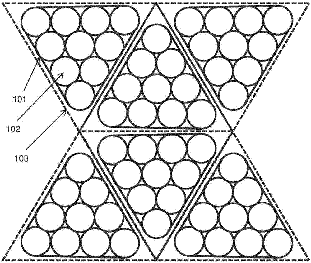
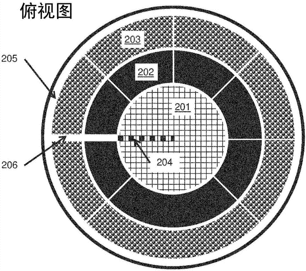
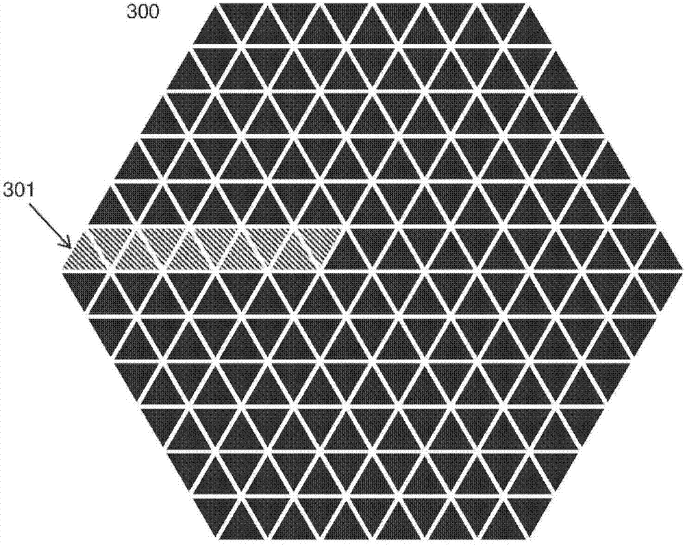
[0014] In order to solve the above problems and allow the reactor to operate efficiently, a solution is proposed whereby the vertical fuel tubes can be moved within the array and removed from the array without the need to lift the vertical fuel tubes above the array. For convenience, the array is divided into multiple fuel assemblies that can move horizontally. Coordinated movement of these fuel assemblies can result in fuel tube movement toward the center of the array as fuel is depleted, and fuel tubes with less than a minimum level of fissile / fertile material move out of the array along an "exit row". New fuel tubes can be added at the outer edge of the array. In this way, the concentration of fissionable material varies with location substantially throughout the life of the reactor.

[0015] Each fuel assembly defines an array cell, an area that surrounds the fuel assembly and does not contain any portion of another fuel assembly. These cells may have any shape of horizo...


PUM


Abstract

The present invention discloses a method of operating a nuclear fission reactor. The reactor includes a reactor core including an array of fuel assemblies and a coolant tank containing a coolant. Each fuel assembly extends generally vertically and includes one or more fuel tubes containing fissionable fuel. The fuel lines are immersed in coolant. The method includes: monitoring and / or modeling the fuel concentration and / or fission rate of each of the fuel assemblies; In this case, the fuel assemblies are moved horizontally within the array to control the rate of fission in the reactor core. The invention also discloses a nuclear reactor implementing the method and a fuel assembly used in the method.

Description

technical field [0001] The present invention relates to the management of fission rates within nuclear reactors. In particular, the invention relates to the management of fission rates within reactors in which fuel is contained within a plurality of fuel tubes. Background technique [0002] Molten salt nuclear reactors are based on a critical mass of fissionable material dissolved in molten salt. This is often called fuel salt. Such fuel salts were pioneered at Oak Ridge National Laboratories in the 1950's to 1970's but have not been successfully commercialized. The fuel salt has several potential advantages over other types of reactors, including the ability to produce fissile uranium from thorium, generation of transuranic actinium waste at much lower levels than uranium / plutonium reactors, operation at high temperatures, avoidance of Accumulation of volatile radioactive fission products in solid fuel rods and a much higher burnup ratio of fissionable materials than in ...

Claims


Application Information

Patent Timeline
Patent Type & Authority Patents(China)
IPC IPC(8): G21C1/22G21C3/33G21C5/02G21C7/30G21C19/20G21C17/10
CPCG21C1/22G21C3/33G21C5/02G21C7/30G21C19/205G21D3/004G21C17/10Y02E30/30Y02E30/00G21C3/335G21C15/28G21C19/07G21D3/001
Inventor 伊恩·理查德·斯科特
Owner 伊恩·理查德·斯科特
Why Eureka
Try Eureka