
Robot control device

一种控制装置、机器人的技术,应用在机器人、程序控制、通用控制系统等方向,能够解决无法平稳地切换控制方式等问题

Active Publication Date: 2017-03-08
FANUC LTD
View PDF10 Cites 2 Cited by
  • Summary
  • Abstract
  • Description
  • Claims
  • Application Information

AI Technical Summary

Problems solved by technology

Moreover, in Japanese Patent Application Laid-Open No. 05-158542, there are problems such as that the control mode cannot be smoothly switched.

Method used


Image

  • Robot control device
  • Robot control device
  • Robot control device

Examples


Embodiment Construction

[0030] Embodiments of the present invention will be described below with reference to the drawings. In the following drawings, the same reference signs are attached to the same components. The scales of these drawings are appropriately changed for easy understanding.

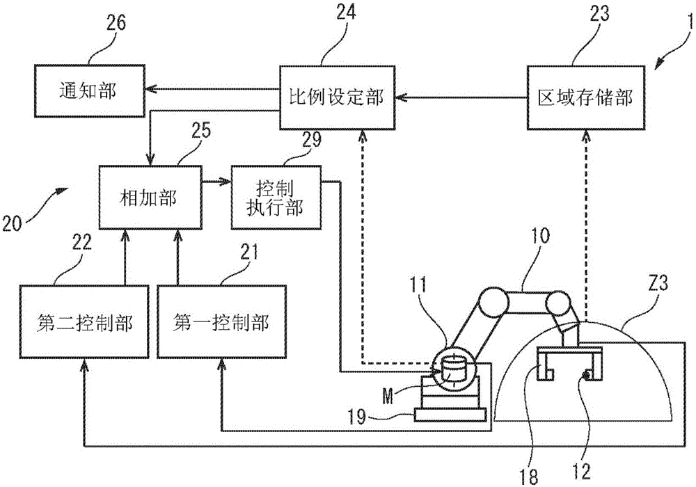
[0031] figure 1 is a block diagram of a robot controller based on the present invention. figure 1 The system 1 shown essentially comprises a robot 10 and a robot controller 20 which controls the robot 10 . The robot 10 is, for example, a six-axis vertical articulated robot. In addition, the robot 10 has a hand 18 at the tip of its arm.

[0032] figure 1 A motor that drives the axis of the robot 10 , such as a motor M, and a position detector such as an encoder E that detects the rotational position of the motor M are shown in . These motors M and encoders E are shown as a representative example, but actually the robot 10 includes a plurality of motors M and encoders E corresponding to the number of axes of...


PUM


Abstract

A robot control device includes a first sensor which is used in a first range including the entirety of the operating range of the robot, a second sensor which is used in a second range including at least a part of the operating range of the robot, and a range storing unit for storing a third range included in both the operating range and the second range. The robot control device also includes a ratio setting unit for setting a ratio between a first control input obtained using the first sensor and a second control input obtained using the second sensor with respect to control inputs to the motor based on the comparison of the third range and the position and posture of the robot, and an addition unit for adding the first control input and the second control input together in accordance with the set ratio.

Description

technical field [0001] The present invention relates to a robot control device for controlling a robot driven by an electric motor. Background technique [0002] Conventionally, only the angular velocity, rotation angle, and torque (current value) of a motor such as a servo motor are fed back to control the robot. In this control method, only an encoder and a current detector to be mounted on the motor are sufficient. [0003] However, robots have been used in various fields in recent years, and conventional control methods may not be sufficient. Therefore, in addition to encoders and current detectors, additional sensors are used to control the robot. [0004] For example, in Japanese Patent Application Laid-Open No. 2012-168926, in order to reduce position deviation due to a transmission error of a reduction gear, etc., full-closed-loop position control using an additional encoder is performed. In addition, in JP 2011-136416 A, position control using a position measurin...

Claims


Application Information

Patent Timeline
Patent Type & Authority Applications(China)
IPC IPC(8): B25J9/12B25J13/08
CPCB25J9/12B25J13/08B25J9/1628G05B2219/40412G05B2219/40488Y10S901/41Y10S901/46
Inventor 小栗健一郎有田创一
Owner FANUC LTD
Learn More