A box-type bridge assembly structure and installation method

An installation method and bridge technology, applied in the direction of bridges, bridge parts, bridge materials, etc., can solve the problems of restricting the span and service life of bridges, unsuitable concrete quality assurance, complicated stress structure, etc., so as to improve vehicle speed and drive comfort. It is beneficial to technical operation and saves construction time.

Active Publication Date: 2018-04-24
LONGJIAN ROAD & BRIDGE
View PDF5 Cites 0 Cited by
  • Summary
  • Abstract
  • Description
  • Claims
  • Application Information

AI Technical Summary

Problems solved by technology

The main defects of the current bridge structure are as follows: First, most of the bridge structure is still a solid structure, that is, a fully enclosed structure. The self-weight of the bridge itself is too large, which seriously restricts the span and service life of the bridge. The bridge complicates the overall stress structure of the bridge, and it is very prone to problems such as uneven stress and shrinkage joints, and there are also problems such as reverse force; secondly, due to the limitation of its own structure, the installation direction is mostly installed by the hoisting method. This has very high requirements for large-scale hoisting equipment, and when the prestress is stretched, the beam body is likely to cause longitudinal cracks along the direction of the pipeline, especially in the negative bending moment area. Because the concrete on the top layer of the prestressed tendon is thin during the hoisting process, the quality of the concrete is not suitable Guaranteed, the beam body is more likely to cause longitudinal cracks along the direction of the pipe

Method used


Image

  • A box-type bridge assembly structure and installation method
  • A box-type bridge assembly structure and installation method
  • A box-type bridge assembly structure and installation method

Examples


Embodiment

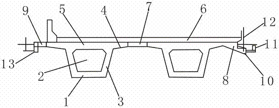
[0023] Embodiment: A box-type bridge assembly structure, including a concrete box girder 1, the concrete box girder 1 is in the shape of an inverted trapezoid, and an inverted trapezoidal hollow interlayer 2 is provided inside the concrete box girder 1, and the concrete box girder 1 is in the shape of an inverted trapezoid A support beam 3 is formed between the beam 1 and the hollow interlayer 2, and a wing beam 4 is fixedly installed on both sides of the concrete box girder 1, and the support surface 5 is formed on the top of the wing beam 4 and the concrete box beam 1, and on the support surface 5 is provided with a concrete pouring layer 6, which is connected by concrete floor joints 7 between adjacent concrete box girders 1, and the concrete box girders 1 at both ends are fixedly installed with cantilever beams 8 and butt-joint beams 9 respectively, and the cantilever beams 8 is composed of a suspension column 10, an anti-slip clamping beam 11 and a docking standard rod 12,...


PUM


Abstract

The invention discloses a box-type bridge assembling structure and a mounting method. The box-type bridge assembling structure comprises concrete box beams, wherein inverted trapezoidal hollow isolating layers are arranged in the concrete box beams; support beams are formed between the concrete box beams and the hollow isolating layers; wing beams are fixedly mounted on the two sides of the concrete box beams; support planes are formed on the tops of the wing beams and the concrete box beams; concrete pouring layers are arranged on the support planes; the adjacent concrete box beams are connected through a concrete joint; and a suspending pulling beam and a butt-joint beam are respectively fixedly mounted on the concrete box beams at two ends. A continuous beam, which has a multi-beam box type hollow structure and is mounted and formed according to a method of first simply supporting and then continuously supporting, has the advantages of high rigidity, few contraction joints and small deformation, can increase the automobile speed and the driving comfort level, and has low dead load, a bridge main body bears the force as a continuous beam structure, and the influence of foundation settlement on the structure is small.

Description

technical field [0001] The invention relates to the technical field of bridge installation technology, in particular to a box-type bridge assembly structure and an installation method. Background technique [0002] With the continuous development of modern bridge-building technology, the current bridge construction has developed from the original simple use of natural materials to direct erection and developed into a reinforced concrete structure. Especially since modern times, with the improvement of construction technology and the development of large-scale hoisting technology, the bridge structure is also developing towards a lighter and stronger direction. Throughout the history of bridge development, modern bridge structures have changed from the early "I" section, "T "Type section, hollow slab girder developed to today's box structure. [0003] Although box-type bridges are widely used at present, the specific structure and installation methods need to be further opti...

Claims


Application Information

Patent Timeline
Patent Type & Authority Patents(China)
IPC IPC(8): E01D2/00E01D2/04E01D19/12E01D21/00E01D101/24
CPCE01D2/00E01D2/04E01D19/125E01D21/00E01D2101/24
Inventor 汤沛林鑫焱
Owner LONGJIAN ROAD & BRIDGE
Why Eureka
Try Eureka