
Rock core oil washing instrument

A technology of oil washing instrument and core, which is applied in the preparation of test samples, etc., can solve the problems of reduced cleaning efficiency, large energy consumption, and slow cleaning effect, and achieve the goal of improving automation, reducing use cost, and improving oil washing efficiency Effect

Inactive Publication Date: 2017-03-08
南通市中京机械有限公司
View PDF5 Cites 7 Cited by
  • Summary
  • Abstract
  • Description
  • Claims
  • Application Information

AI Technical Summary

Problems solved by technology

[0003] Existing core oil washing machines often use high-temperature and high-pressure multi-functional oil washing machines, which will involve the following problems: 1. When the solvent vapor of the oil washing machine is cooled in the condensation chamber, the cooling water used for cooling is directly connected to the cooling water inlet from the tap water pipeline Enter the condensation chamber, discharge into the sewer from the cooling water outlet, the waste of water resources is serious, and the temperature of the tap water is affected by the ambient temperature, and the cooling temperature changes from time to time, which affects the cooling effect of the solvent vapor
2. The remaining gas in the condensation chamber is directly discharged into the air, and the tiny solvent liquid carried in the remaining gas will cause environmental pollution
3. The cycle control of the oil washing instrument is mainly to control the pneumatic valve according to the time, but due to the influence of heating temperature and ambient te

Method used


Image

  • Rock core oil washing instrument
  • Rock core oil washing instrument
  • Rock core oil washing instrument

Examples


Embodiment Construction

[0013] In order to deepen the understanding of the present invention, the present invention will be further described below in conjunction with the embodiments and accompanying drawings. The embodiments are only used to explain the present invention and do not constitute a limitation to the protection scope of the present invention.

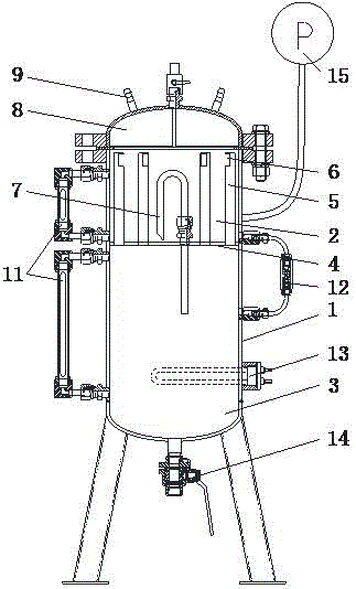
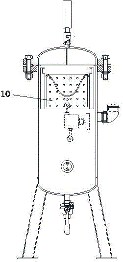
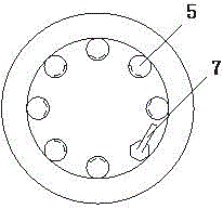
[0014] Such as Figure 1-3 A kind of core oil washing instrument shown, comprises main body 1, and main body 1 is divided into rock core chamber 2 of upper part and the heating chamber 3 of lower part, and rock sample basket 10 is placed in rock core chamber 2, and rock sample basket 10 surface There are through holes, and the core chamber 2 and the heating chamber 3 are separated by a sealing partition 4, and seven steaming pipes 5 are evenly distributed on the sealing partition 4, and the opening below the steaming pipe 5 leads to the heating chamber 3, and the steaming There are gas outlets 6 above the tubes 5. After the liquid in the heating ...


PUM


Abstract

The invention discloses a rock core oil washing instrument comprising a main body. The main body is divided into an upper rock core chamber and a lower heating chamber, the rock core chamber and the heating chamber are partitioned by a seal partition, a plurality of steaming-condensing pipes are evenly distributed on the seal partition, an opening in the lower portion of every steaming-condensing pipe leads to the heating chamber, a gas outlet is formed in the upper portion of every steaming-condensing pipe, the seal partition is provided with a flood discharge pipe, the upper portion of the rock core chamber is connected with a condensing chamber through bolts, a rock sample basket is arranged in the rock core chamber, through holes are formed in the surface of the rock sample basket, the rock core chamber and the heating chamber are provided with liquid level meters, liquid in the heating chamber is heated by a heater, a ball valve is arranged at the outer bottom of the heating chamber, and a pressure gauge is externally connected with the rock core chamber. The rock core oil washing instrument has the advantages that cleaning requirements of geological rock cores can be met, oil washing efficiency can be improved, environmental protection and cyclic utilization of heat can be achieved, automation degree can be increased, use cost can be reduced, and temperature and pressure can be controlled automatically.

Description

technical field [0001] The invention relates to a rock core oil washing device, in particular to a rock core oil washing instrument. Background technique [0002] The quality and speed of geological core cleaning will affect the acquisition of core data and the evaluation results of geological resources. The oil washing instrument is an indispensable instrument for core cleaning and drying, and is used to clean crude oil and its soluble substances in oily cores. In order to meet the cleaning requirements of geological cores, a core oil washing instrument is needed. [0003] Existing core oil washing machines often use high-temperature and high-pressure multi-functional oil washing machines, which will involve the following problems: 1. When the solvent vapor of the oil washing machine is cooled in the condensation chamber, the cooling water used for cooling is directly connected to the cooling water inlet from the tap water pipeline Enter the condensation chamber, discharg...

Claims


Application Information

Patent Timeline
IPC IPC(8): G01N1/34
CPCG01N1/34
Inventor 王华
Owner 南通市中京机械有限公司
Learn More