
Method for fluid identification by using seismic low-frequency information

A fluid identification and fluid technology, applied in seismic signal processing, seismology for logging records, etc., can solve problems such as unclear fluid relationship, unstable oil and gas identification method, low signal-to-noise ratio of high-frequency seismic signals, etc. , to achieve the effects of being easy to popularize and apply, improving the coincidence rate of fluid prediction, and eliminating the influence of high-frequency noise

Active Publication Date: 2017-03-08
CHINA PETROLEUM & CHEM CORP +1
View PDF2 Cites 8 Cited by
  • Summary
  • Abstract
  • Description
  • Claims
  • Application Information

AI Technical Summary

Problems solved by technology

However, there are still the following problems in the application of seismic frequency attributes to fluid identification: the method of using pre-stack elastic parameters to identify fluids has high accuracy, but the calculation load is large and the efficiency is low; the original frequency components may be reconstructed during the processing of conventional post-stack seismic data. Either the low-frequency component is filtered out or the noise is not completely suppressed. If the post-stack seismic data that loses the frequency components sensitive to oil and gas reservoirs is used for oil and gas detection, false information will be generated; many frequency attribute fluid identification factors have great influence on fluid Sensitivity varies, relationship to fluid is unclear
However, for rock reservoirs with strong heterogeneity, the complexity of the seismic wavefield characteristics makes the prediction of gas layers by high-frequency attenuation gradient attributes highly multi-solution, and it is difficult to realize the correct judgment of gas layers and water layers. Moreover, the signal-to-noise ratio in the high-frequency band of the seismic signal is low, which also leads to the instability of oil and gas identification methods using conventional seismic frequency attributes

Method used


Image

  • Method for fluid identification by using seismic low-frequency information
  • Method for fluid identification by using seismic low-frequency information
  • Method for fluid identification by using seismic low-frequency information

Examples


Embodiment Construction

[0056] The implementation of the present invention will be described in detail below in conjunction with the accompanying drawings and examples, so that implementers of the present invention can fully understand how the present invention uses technical means to solve technical problems, and achieve the realization process of technical effects and according to the above-mentioned realization process The present invention is implemented concretely. It should be noted that, as long as there is no conflict, various features in the embodiments of the present invention can be combined with each other, and the formed technical solutions are all within the protection scope of the present invention.

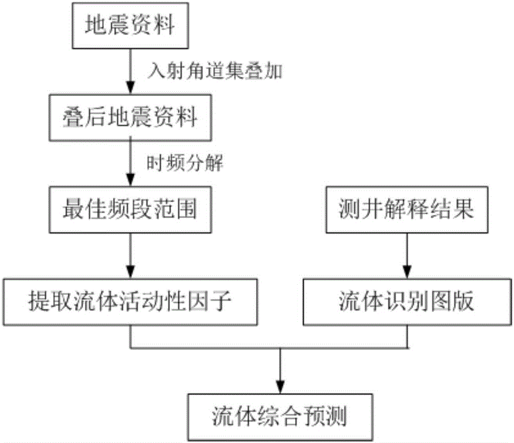
[0057] The following is based on the attached figure 1 The flow chart in will describe the implementation process of the method of the present invention in detail. The steps shown in the flowcharts of the figures can be performed in a computer system comprising, for example, a set of com...


PUM


Abstract

The invention relates to a method for fluid identification by using seismic low-frequency information. The method comprises: on the basis of seismic data, a fluid activity factor is extracted; and fluid identification is carried out by combining logging information. The fluid activity factor is a dimensionless parameter depending on fluid activity. According to the method provided by the invention, the fluid activity factor that is a dimensionless parameter depending on fluid activity is introduced into the fluid identification and evaluation field, so that the fluid prediction agreement rate is improved effectively, the reservoir stratum fluid type is determined and predicted effectively, and the guidance and basis are provided for further exploitation and development. Meanwhile, the method is easy to promote and apply to exploitation and development of various stratums, so that the application prospects are broad.

Description

technical field [0001] The invention belongs to the field of oil and gas exploration and development, and in particular relates to a method for fluid identification using seismic low-frequency information. Background technique [0002] With the continuous improvement of high-precision time-frequency analysis technology, the research on fluid identification technology using low-frequency and high-frequency information of seismic data has become a new hot spot. However, there are still the following problems in the application of seismic frequency attributes to fluid identification: the method of using pre-stack elastic parameters to identify fluids has high accuracy, but the calculation load is large and the efficiency is low; the original frequency components may be reconstructed during the processing of conventional post-stack seismic data. Either the low-frequency component is filtered out or the noise is not completely suppressed. If the post-stack seismic data that loses...

Claims


Application Information

Patent Timeline
IPC IPC(8): G01V1/50
Inventor 魏水建王丹贾跃玮
Owner CHINA PETROLEUM & CHEM CORP
Learn More