

Power distribution network fault location method based on fault indicators
A fault indicator and distribution network fault technology, applied in the field of power system, can solve the problems of unrealistic judgment of fault location, difficulty in determining fault section, easy to make wrong judgment, etc., achieving fast calculation speed, low price and low cost. The effect of power consumption
- Summary
- Abstract
- Description
- Claims
- Application Information
AI Technical Summary
Problems solved by technology
Method used
Image

Examples
Embodiment 1
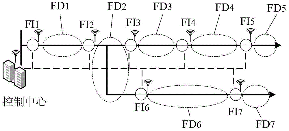
[0035] Such as figure 1 As shown, there are 7 fault indicators in the topology of the distribution network, the direction of the power flow of the distribution network line is the positive direction, the power node in the distribution network is the starting number, and the geographical location of the fault indicators in the grid is , the fault indicator nodes are sequentially numbered as FI 1 -FI 7 , for the lines between the nodes and the lines after the end node, the section number is FD 1 -FD 7 .
[0036] The correlation matrix construction unit of the master station control center generates the correlation matrix:
[0037] The node injection current is the current flowing into the node, and the line current is the current flowing in the branch connected to the two nodes. The correlation matrix represents the relationship between the injection current and the line current, which can be determined through the topological structure of the distribution network. Construc...
Embodiment 2
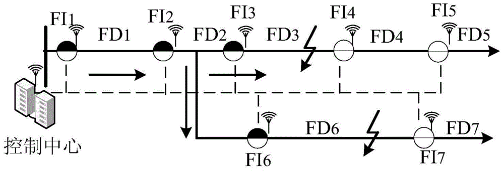
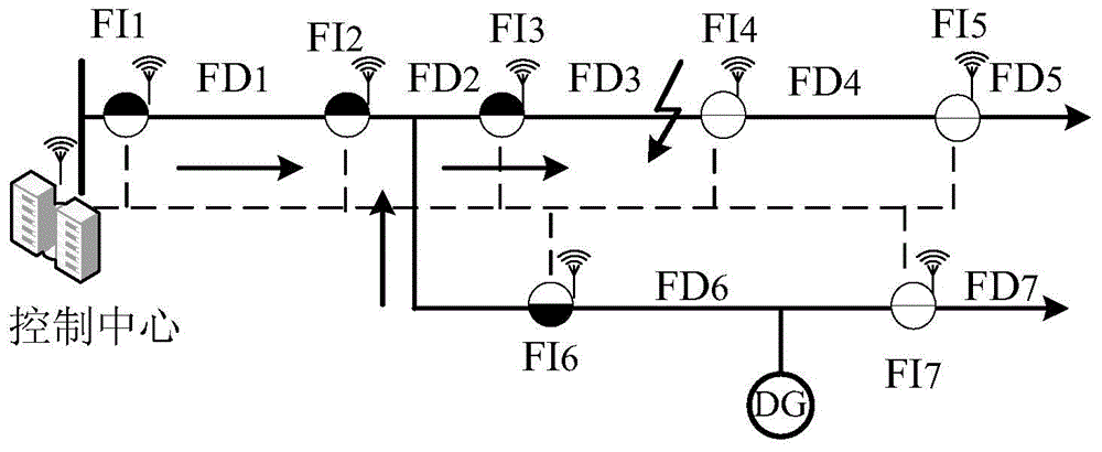
[0048] image 3 It is a topological structure diagram of a distribution network including a distributed power supply DG, and the node numbers, section numbers, and building an association matrix A are the same as those in Embodiment 1. The fault indicator has the function of detecting the direction of the current, and can act according to the direction of the current. Fault occurs in FD 3 segment. Because the distributed power supply DG is connected to the line, the direction of the power flow in the line has changed, that is, the system contains two power supplies for power supply, the injection current and the line current are no longer a single radiation type, and the current direction provided by the substation power supply is set is the positive direction. When the fault indicator detects that the fault current is in the same direction as the positive direction, the fault indicator triggers an action and sends the status information to the master station control center...
Embodiment 3
[0056] Figure 4 It is a topological structure diagram of the distribution network including 7 fault indicators, and the node numbers, section numbers, and building correlation matrix A are the same as those in Embodiment 1. Fault occurs in FD 5 section, where the fault indicator FI 4 Refuse to move. The fault location unit of the master station control center collects the FI 1 、FI 2 、FI 3 and FI 5 The status information of , and the trigger vector is generated as follows:
[0057] I L =[1 1 1 0 1 0 0] T
[0058] The fault location unit operates according to the following matrix operation formula:
[0059] I FD =A -1 × I L
[0060] Get the fault location vector:
[0061] I FD =[0 0 1 -1 1 0 0] T
[0062] I FD The third element and the fifth element are 1, then there are three possible fault situations, namely: the fault is in the section FD 3 , the fault is in section FD 5 , section FD 3 and section FD 5 Simultaneous faults occur, thus forming three faul...
PUM
 Abstract
Description
Claims
Application Information