[0153] Example:
[0154] The present invention combines the specific data of a certain passenger car as the basic vehicle model to introduce the independent evaluation working condition of the front anti-collision beam assembly proposed by the present invention and verify the validity of the independent working condition, and use the independent working condition to carry out the front anti-collision condition. The process of lightweight design of the impact beam assembly.
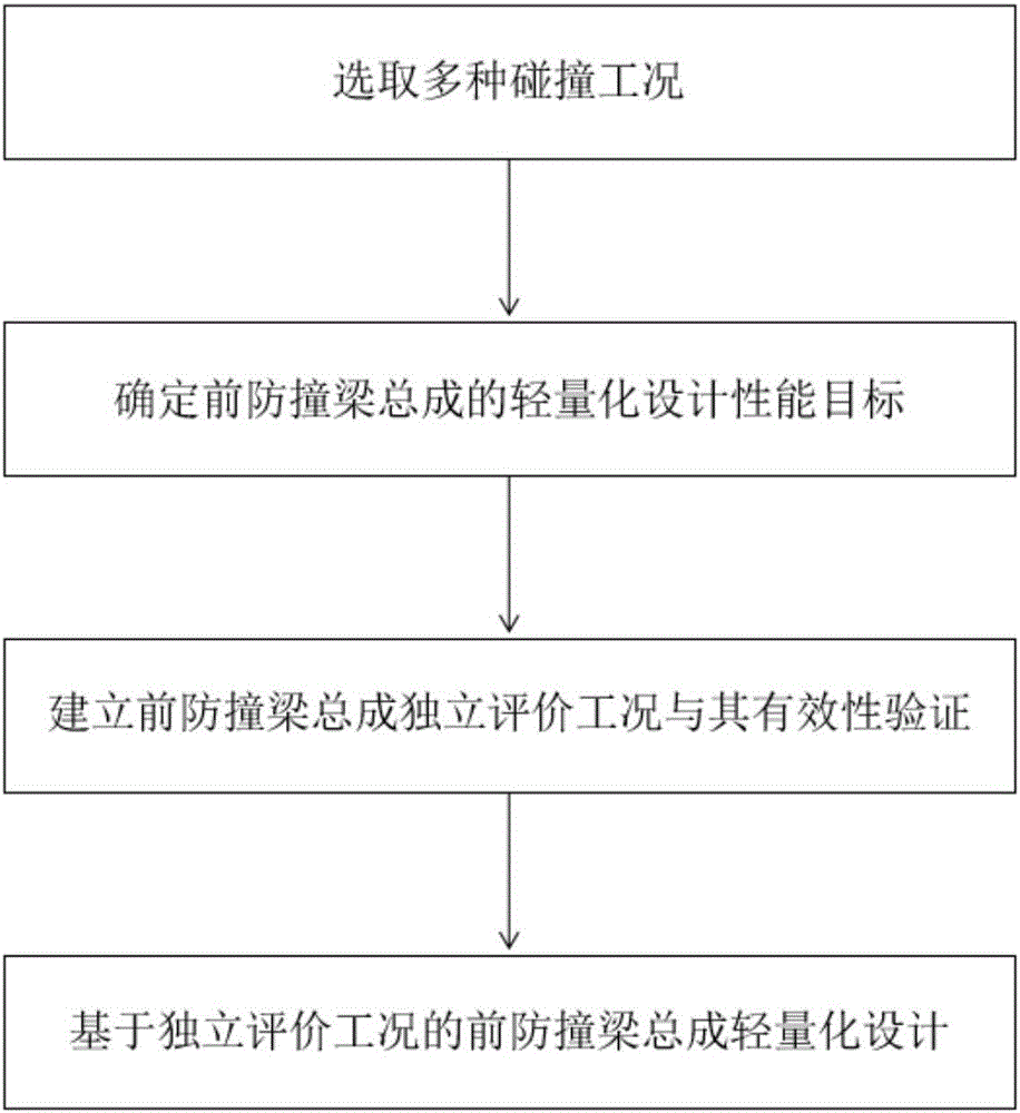
[0155] 1. Select a variety of collision conditions
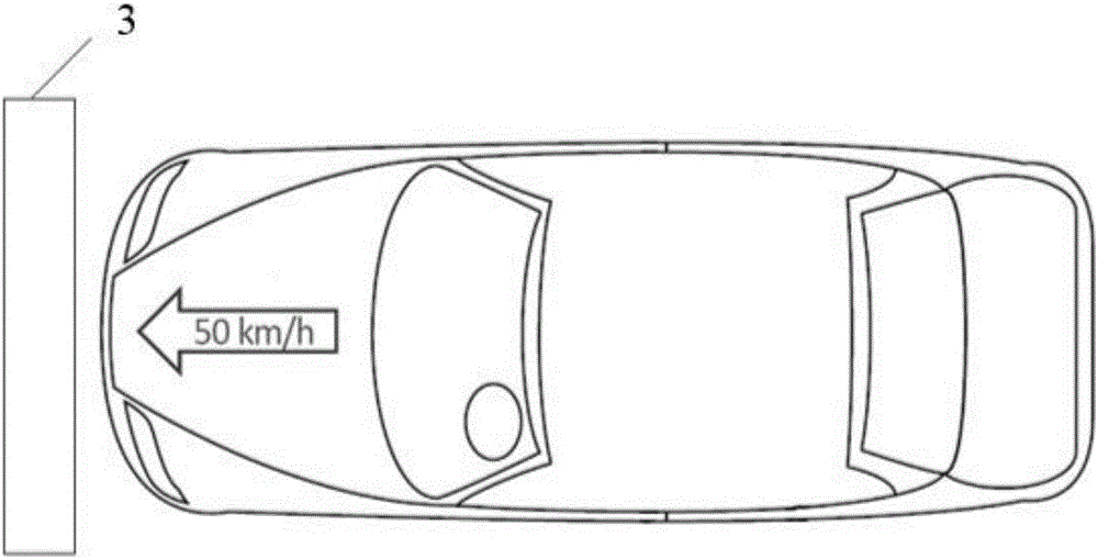
[0156] The front anti-collision beam assembly of the base model is designed respectively under three working conditions: frontal full-width high-speed collision condition, frontal 40% overlapping low-speed collision condition and static pressure condition.
[0157] 2. Determine the performance target of the front crash beam assembly
[0158] 1) Determine the lightweight design performance target of the front anti-collision beam assembly based on the frontal full-width high-speed collision condition
[0159]With the help of finite element software, the collision simulation test based on the frontal full-width high-speed collision condition is carried out on the basic vehicle, and the collision waveform of the basic vehicle is obtained and simplified into a double-step wave such as Figure 13 The coordinate values of each feature point are shown in Table 1.
[0160] Table 1. Coordinate values of each feature point of simplified double-step wave
[0161] A B C D E F X(s) 0 0.0073 0.0295 0.0328 0.0538 0.0674 Y(m/s 2 )
[0162] see Figure 14 and Figure 15 , take the simplified waveform as the target waveform, and convert the acceleration-time curve of the target waveform into an acceleration-displacement curve such as Figure 14 shown in. Then, the energy density curve is obtained by integrating, such as Figure 15 shown. The energy absorption of the energy absorption box accounts for 70% of the space in the vertical direction. According to the acceleration-displacement curve integration of the target waveform, the total absorption energy of the longitudinal space is obtained as E_0=46.9kJ, and the energy absorption of the single-sided energy absorption box E is calculated as 46.9×0.7=32.8kJ. The longitudinal length L of the energy-absorbing box is 302mm, the compression amount is 218mm, and the compression coefficient k of the compression distance is 0.85. The average axial structural force of the single-sided energy-absorbing box is calculated from Equation 1 to be 75kN.
[0163] see Figure 16 , It can be seen from the figure that the first and second peaks of the section force curve in the base model are 29061N and 83034N respectively. The total deviation of the two section force peaks before and after optimization is Δ=∣T_1-29061∣+∣T_2-83034∣, The scale factor δ=Δ/(29061+83034)<8%, that is, Δ<8968N.
[0164] 2) Determine the lightweight design performance target of the front anti-collision beam assembly based on the frontal 40% overlapping low-speed collision condition
[0165] With the help of finite element software, the collision simulation test based on the frontal 40% overlapping low-speed collision condition was carried out on the basic vehicle, and the contact force-displacement curve of the collision simulation was obtained and simplified to obtain the coordinates of each feature point of the simplified contact force-displacement curve as shown in Table 2;
[0166] Table 2 Coordinate values of each feature point of the simplified curve
[0167] A B C D E X(mm) 0 45 49 110 120 Y(kN) 0 86 78 78 97
[0168] The limit distance between the anti-collision beam 1 and the radiator 9 of the base model is 115mm. It can be seen from Table 2 that the maximum intrusion displacement of the base model under the condition of a frontal 40% overlapping low-speed collision is 120mm>115mm, so the body structure needs to be optimized.
[0169] Through simulation, it is known that the ultimate average structural force F_l=125kN for the yielding of the longitudinal beam, then the ultimate average structural force F of the energy-absorbing box c =F L /1.2/1.2=87kN, the peak force F of the anti-collision beam 1 a <1.2F c =104kN.
[0170] see Figure 17 , According to the above constraints, the coordinates of each feature point of the target contact force-displacement curve are obtained by applying energy conservation, as shown in Table 3.
[0171] Table 3 Coordinate values of each feature point of the target waveform
[0172] A B C D E X(mm) 0 45 51 110 115 Y(kN) 0 92 84 84 97
[0173] Therefore, it can be seen that the performance target of the front bumper beam assembly in the low-speed collision condition with a frontal 40% overlap is set as: the intrusion of the bumper beam 1 is 115mm, and the average structural force of the energy absorbing box is F_m=84kN.
[0174] 3) Determine the performance target of lightweight design of front crash beam assembly based on static pressure conditions
[0175] The peak value of the contact reaction force of the base model is 16.3 kN. Taking the peak static pressure reaction force of the anti-collision beam as the performance target, it is constrained to be greater than 105% of the static pressure result of the base model, but not more than 130%, that is, greater than 17.1kN and less than 21.2kN.
[0176] 3. Establish independent evaluation conditions and effectiveness verification of front anti-collision beam assembly
[0177] 1) Establish an independent evaluation condition of the front anti-collision beam assembly based on the frontal full-width high-speed collision condition
[0178] see Figure 11 , to establish an independent evaluation condition based on a frontal full-width high-speed collision. In the passive collision form, the rear end of the front anti-collision beam assembly is fixed and restrained, the rigid barrier 3 is used to hit the front anti-collision beam assembly, and a rigid wall 14 is established in an independent working condition to replace the radiator and other components.
[0179] The initial kinetic energy E of the rigid barrier 3 in the independent working condition is preliminarily determined according to the energy absorption of the front anti-collision beam assembly in the vehicle collision af = 36kJ, assuming that the initial speed of the rigid barrier movement is consistent with the initial speed of the vehicle collision and is still 50km/h. By the formula E = 1/2mv 2 , considering energy losses such as rebound kinetic energy and frictional energy, by attaching Figure 11 The initial kinetic energy is corrected according to the energy absorbed by the front anti-collision beam assembly in the vehicle collision, and the initial kinetic energy E of the rigid barrier 3 is finally determined. af = 37.9kJ and mass m of rigid barrier 3 f =396kg.
[0180] 2) The validity verification of the independent evaluation condition of the front anti-collision beam assembly based on the frontal full-width high-speed collision condition
[0181] The modified independent working condition is simulated and analyzed, and the independent evaluation working condition of the front anti-collision beam assembly under the frontal full-width high-speed collision condition and the deformation mode of the front anti-collision beam assembly under the vehicle working condition are compared, and two kinds of working conditions are found. During the collision, the anti-collision beam 1 is flattened first, and then the energy-absorbing boxes on the left and right sides begin to be crushed and deformed axially. It can be seen that the deformation modes of the front anti-collision beam assembly under the two working conditions are basically the same, and the intrusion amount of the anti-collision beam 1 is equal.
[0182] Table 4 shows the comparison of the energy absorption of each component of the front anti-collision beam assembly under the condition of the frontal full-width high-speed collision and the complete vehicle condition. It can be seen from Table 4 that the energy absorption error of each component is small. , within the acceptable range, it is considered that the energy absorption effect of the front anti-collision beam assembly under independent working conditions is consistent with that in the whole vehicle.
[0183] Table 4 Comparison of energy absorption of each component of the front anti-collision beam assembly under vehicle conditions and independent conditions
[0184]
[0185] In the independent working condition, the section forces at three positions of section No. 1, No. 2, and No. 3 are extracted and compared with the section forces at the longitudinal beam of the whole vehicle, as shown in the appendix. Figure 17 It is found that the three section forces extracted in the independent working condition and the section force of the longitudinal beam of the whole vehicle have a very good agreement in the early stage of the collision, and the deformation stage of the front anti-collision beam assembly occurs in the early stage of the collision, indicating that the independent The working conditions well reflect the cross-sectional force transmission data of the front anti-collision beam assembly in the vehicle. Because the section force at the rear section of the energy-absorbing box on the left and right sides in the independent working condition cannot reflect the section force when the longitudinal beam yields, its peak value is larger than that of the vehicle.
[0186] By comparing the four aspects of deformation mode, energy absorption, section force and intrusion amount between the independent working condition of the frontal full-width high-speed collision condition and the vehicle working condition, it is verified that the independent working condition based on the frontal full-width high-speed collision is established. effectiveness.
[0187] 3) Establish an independent evaluation condition of the front anti-collision beam assembly based on the frontal 40% overlapping low-speed collision condition
[0188] see Figure 12 , to establish an independent evaluation condition of the front anti-collision beam assembly based on the frontal 40% overlapping low-speed collision condition. The rear end of the energy-absorbing box is fixed, and the rigid barrier hits the front anti-collision beam assembly. According to the energy absorption of the front anti-collision beam assembly in the vehicle collision, the initial kinetic energy of the rigid barrier in the independent working condition is preliminarily determined to be E_ar=6.6kJ, and the initial collision speed is assumed to be still 15km/h. From the conservation of energy, the mass of the rigid barrier is obtained, and the energy losses such as rebound kinetic energy and friction energy are considered. Figure 12 The initial kinetic energy of the rigid barrier is corrected according to the energy absorbed by the front anti-collision beam assembly in the vehicle collision, and the initial kinetic energy of the rigid barrier E_ar=6.9kJ and the mass of the rigid barrier are finally determined. m_r=800kg.
[0189] 4) Validity verification of independent evaluation conditions based on frontal 40% overlapping low-speed collision pre-collision beam assembly
[0190] Comparing the deformation mode of the front anti-collision beam assembly in the frontal 40% overlapping low-speed collision condition and the vehicle condition, it is found that the left energy-absorbing box and the right energy-absorbing box are both in the collision process under the two working conditions. The box first undergoes axial crushing deformation. When the anti-collision beam 1 produces a plastic hinge, the two induction grooves at the upper end of the energy-absorbing box are deformed, and then the two induction grooves at the lower end are deformed. It can be seen that the deformation under the two working conditions The pattern is basically the same.
[0191] see Figure 19 , the figure shows the intrusion curve of the front anti-collision beam under the independent working condition. It can be seen that the maximum intrusion amount of the anti-collision beam 1 under the independent working condition is 119.9mm, which is slightly different from the maximum intrusion amount of the vehicle working condition of 120mm. neglect.
[0192] Table 5 shows the comparison of the energy absorption of each component of the front anti-collision beam assembly in the independent working condition and the vehicle working condition. It can be seen from Table 5 that the error between the two is small, and within the acceptable range, it is considered that the front anti-collision beam under the independent working condition is The energy absorption effect of the assembly is the same as that in the whole vehicle.
[0193] Table 5 Comparison of the energy absorption of each component of the front anti-collision beam assembly under the vehicle working condition and the independent working condition
[0194]
[0195] see Figure 20 , In the independent working condition based on the frontal 40% overlapping low-speed collision, the section forces at the three positions of the 1st, 2nd, and 3rd sections are also extracted and compared with the section force at the longitudinal beam of the whole vehicle, and the independent working conditions are found from the figure. The three cross-sectional forces extracted from 2000 have a very good agreement with the cross-sectional force of the longitudinal beam in the whole vehicle, indicating that the independent working condition reflects the information of the cross-sectional force transmission of the front anti-collision beam assembly in the whole vehicle.
[0196] By comparing the four aspects of deformation mode, energy absorption, section force and intrusion amount between the independent working condition of the frontal 40% overlapping low-speed collision and the vehicle working condition, the validity of the establishment of the independent working condition is verified, and it is considered that the independent working condition is used. It can reflect the collision information of the front anti-collision beam assembly in the whole vehicle.
[0197] 4. Lightweight design of front anti-collision beam assembly based on independent evaluation conditions
[0198] 1) The design goal of the anti-collision beam of the base model
[0199] According to the specific data of the basic model, the design goals of the anti-collision beam lightweight problem are as follows:
[0200] Constraints: Front full width high-speed conditions: Δ section force <8968N
[0201] Front 40% overlapping low speed condition: intrusion <115mm
[0202] Static pressure condition; 17.1kN <21.2kN
[0203] Optimization objective: minimum quality Min(M)
[0204] In this way, the lightweight design of the anti-collision beam is carried out.
[0205] 2) Design goals of the energy-absorbing box for the base model
[0206]According to the specific data of the base model and the analysis and discussion of the second step, the average structural force of the single-sided energy-absorbing box is required to be 75kN in the frontal full-width high-speed collision condition, and in the frontal 40% overlapping low-speed collision condition, a single The average structural force of the side energy-absorbing box is 84kN. Considering the inclusion relationship between the performance requirements of the energy-absorbing box under different working conditions, the present invention takes the single-side average structural force of 84kN as the design goal of the lightweight design of the energy-absorbing box.
[0207] 3) Lightweight scheme design of front anti-collision beam assembly
[0208] 1) Lightweight design of anti-collision beams for basic models
[0209] see Figure 21 , For the aluminum alloy 6061T6 anti-collision beam in the form of a Japanese-shaped cross-section, the present invention takes the thickness t1 of the front and rear side walls of the anti-collision beam, the thickness t2 of the upper and lower side walls of the beam and the thickness t3 of the middle rib as design variables. The design parameters of the beam wall thickness are shown in the figure, and the upper and lower limits are set as shown in Table 6.
[0210] Table 6 Design parameter limits for Japanese-shaped cross-section
[0211]
[0212]
[0213] The present invention selects the optimal Latin hypercube method to design the experimental scheme, with a total of 12 groups. In the established independent working conditions, the performance index is used as the output result for simulation calculation, and the results are shown in Table 7.
[0214] Table 7. Simulation results of the test plan of the Japanese-shaped cross section
[0215]
[0216] According to the data in Table 7, find the relationship between the parameters of the sun-shaped cross-section anti-collision beam and its performance, and use the Isight software to establish an approximate response surface model. Taking the performance design objective as the constraint condition, the optimization algorithm is used to optimize the design of each wall thickness of the anti-collision beam to find the optimal solution, that is, the optimal combination of parameters of the anti-collision beam that meets the performance requirements is obtained, as shown in Table 8. It can be seen that the lightweight effect of the aluminum alloy anti-collision beam with the Japanese-shaped cross-section can reach 30.4%. The optimization results of the anti-collision beam with the Japanese-shaped section are substituted into the finite element model for verification.
[0217] Table 8 Optimization results of the zigzag section
[0218] Optimization Results t1(mm) t2(mm) t3(mm) Mass(kg) Lightweight effect Japanese glyph 3.39 2.1 3 3.36 30.4%
[0219] 2) Lightweight energy-absorbing box design for basic models
[0220] see Figure 22 , the present invention will use the CAE method to design the structure of the energy-absorbing box. The loading method of the single-sided energy-absorbing box in the finite element software is shown in the figure. The six degrees of freedom at the bottom of the energy-absorbing box are constrained, and the rigid barrier must be The initial velocity hits the energy-absorbing box to crush it completely.
[0221] The present invention adopts the method of orthogonal test to analyze the effect of each parameter of the energy-absorbing box on the performance of the energy-absorbing box. The orthogonal experiment method is to use a neatly arranged table—orthogonal table to carry out overall design, comprehensive comparison and statistics of the test. Analysis, to achieve better experimental results through a small number of experiments. Among them, there are 4 factors in the orthogonal test, namely section form, material, thickness and inclination angle. The section form has 6 levels (variation of influencing factors), which are rectangle, square, hexagon, octagon, twelve deformation, and cross. There are 3 levels each for material, thickness and inclination, as shown in Table 9. Table 10 is the mixed orthogonal test table. The average structural force and mass of the energy-absorbing box were measured, and the ratio of the average structural force F to the mass M was taken as the evaluation index. The larger the ratio, the better the performance of the energy-absorbing box per unit mass.
[0222] Table 9 Schematic diagram of orthogonal test factors and levels
[0223]
[0224] Table 10 Mixed Orthogonal Test Table
[0225]
[0226]
[0227] The data analysis of the F/M values of 18 groups of orthogonal tests is carried out, as shown in Table 11, it can be seen that among the cross-sectional forms, the cross-shaped is the best; the energy-absorbing box without inclination angle is better than the inclined angle; Among them, DP780 is the best, followed by aluminum alloy 6061T6; the performance of the energy-absorbing box gradually increases with the increase of its thickness. The analysis of variance shows that the larger the variance, the more sensitive the factor is, and the more obvious the influence effect is. The primary and secondary order of the influence of the four factors in this experiment are the section form, thickness, material and inclination angle respectively. The optimal parameter combination method is that the cross-sectional form of the energy-absorbing box is cross-shaped and has no inclination angle. When the material is DP780 and the thickness is 2mm, the performance of the energy-absorbing box is the best.
[0228] Table 11 Test result analysis table
[0229]
[0230] 4) Performance verification of the lightweight scheme of the front anti-collision beam assembly
[0231] In summary, the following lightweight solutions are adopted:
[0232] The anti-collision beam 1 is a lightweight solution. The cross-section of the anti-collision beam 1 is a Japanese shape, and the material is aluminum alloy 6061T6;
[0233] The light-weight solution of the energy-absorbing boxes on the left and right sides, the cross-sectional form is cross-shaped, and the material is DP780. The lightweight scheme is integrated with the whole vehicle for simulation calculation. In the frontal full-width high-speed collision condition, the first step height G1 and the second step height G2 of the simplified waveform of the collision waveform are selected to compare with the target waveform; in the frontal 40 In the % overlapped low-speed collision condition, the maximum intrusion amount and the average structural force of the energy-absorbing box are compared with the target contact force displacement curve, and the error value is not more than 5%, which verifies the feasibility of the lightweight scheme.
[0234] To sum up, the present invention selects three working conditions: frontal full-width high-speed collision condition, frontal 40% overlapping low-speed collision condition and static pressure condition to analyze and analyze the performance of the front anti-collision beam assembly of the basic vehicle. Discuss and determine the lightweight design performance objectives of the front crash beam assembly under different operating conditions. The significance of establishing the independent evaluation condition of the front anti-collision beam assembly is introduced, and the effective evaluation index established by the independent evaluation condition is discussed. , The independent evaluation condition of the frontal 40% overlapping low-speed collision condition, the validity of the establishment of the independent evaluation condition of the front anti-collision beam assembly is verified by four indicators: deformation mode, energy absorption, section force and intrusion amount. And use the established independent working conditions to provide guidance for the independent evaluation working conditions and lightweight design of the front crash beam assembly. The establishment of this independent working condition avoids the disadvantage that the performance verification of the front anti-collision beam assembly can only be carried out in the whole vehicle, and saves a lot of test and simulation calculation time.