Terminal antenna based on metal rear shell and terminal

A technology for metal back shells and terminal antennas, applied to metal shells, antenna devices with additional functions, antennas, etc., can solve problems that affect the appearance of mobile phones, reduce antenna performance, and affect aesthetics

Active Publication Date: 2017-03-08
浙江丰泽科技有限公司
View PDF7 Cites 3 Cited by
  • Summary
  • Abstract
  • Description
  • Claims
  • Application Information

AI Technical Summary

Problems solved by technology

While all-metal mobile phones improve the quality and grade of mobile phones, the performance of the antenna is also reduced due to the natural signal shielding characteristics of metal. challenge
[0003] In order not to affect the performance of the antenna, the performance of the antenna can be achieved by slotting the metal back shell, but too many slots affect the appearance. At present, the three-section all-metal back shell has become a trend in smart phone design, and the ratio of the upper and lower metal sections is larger. It has become the focus of competition among various mobile phone manufacturers, but judging from the current popular mobile phone styles on the market, the upper and lower metal parts are still too wide, usually between 5mm and 15mm, resulting in obvious non-conductive plastic areas at the broken seams. Seriously affects the appearance of the phone

Method used


Image

  • Terminal antenna based on metal rear shell and terminal
  • Terminal antenna based on metal rear shell and terminal
  • Terminal antenna based on metal rear shell and terminal

Examples


Embodiment Construction

[0052] In order to facilitate the understanding of those skilled in the art, the following further description of the present invention in conjunction with the accompanying drawings cannot be used to limit the protection scope of the present invention. It should be noted that the embodiments in this application and various modes in the embodiments can be combined with each other if there is no conflict.

[0053] It should be understood that the specific embodiments described herein are only used to explain the present invention, but not to limit the present invention.

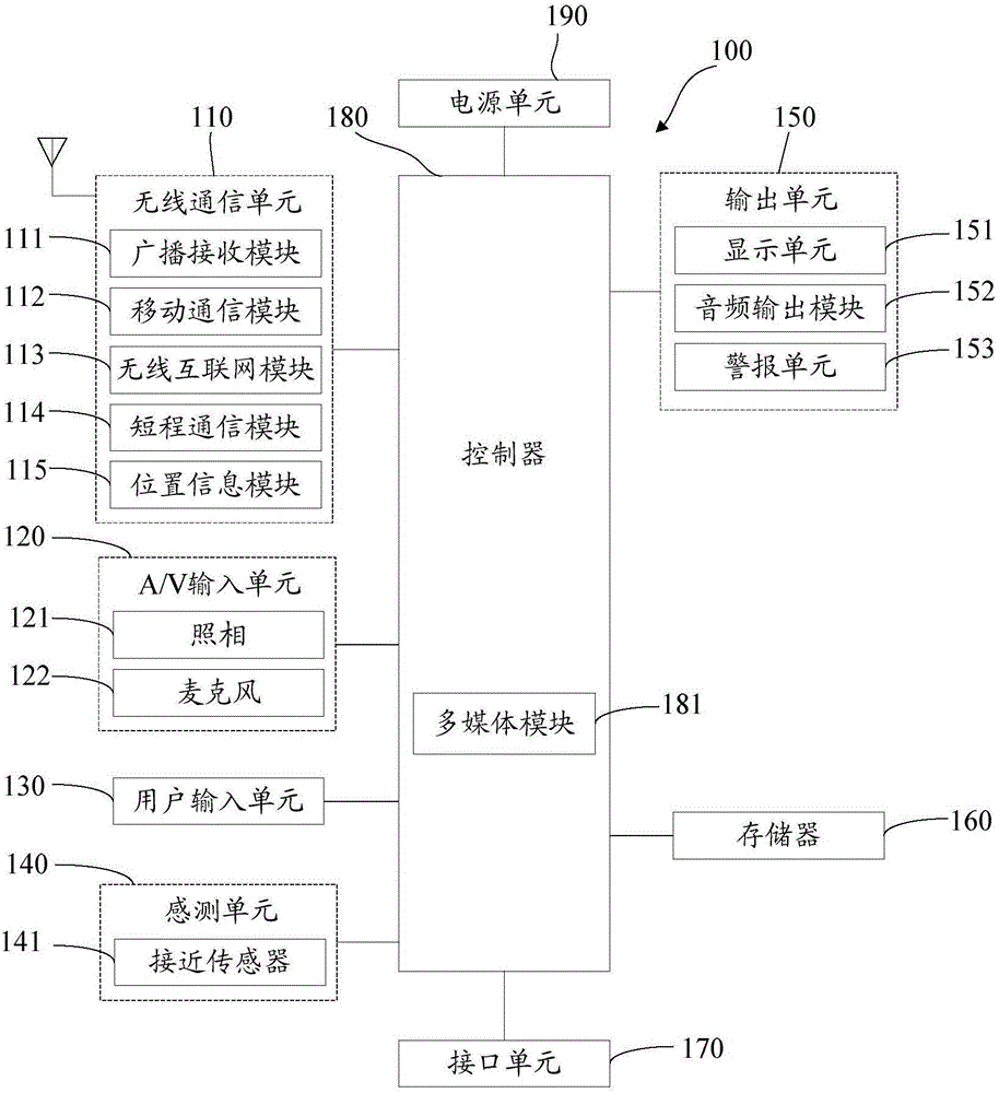
[0054] Now, a mobile terminal implementing various embodiments of the present invention will be described with reference to the accompanying drawings. In the following description, the use of suffixes such as “module”, “part” or “unit” used to denote elements is only used to facilitate the description of the present invention, and has no specific meaning in itself. Therefore, "module" and "component" can be mixed. ...


PUM


Abstract

The invention discloses a terminal antenna based on a metal rear shell and a terminal. The terminal antenna comprises a metal rear shell, a conducting medium, a grounding element, a feed matching network and a feed point, wherein a gap is formed in one end of the metal rear shell, and the gap is used for partitioning the metal rear shell into a bottom metal frame and a back metal plate, wherein the bottom metal frame serves as an antenna radiating unit, and the back metal plate serves as ground; the conducting medium is arranged on the side edge or top of the metal frame of the metal rear shell; at least one point on the conducting medium is coupled or short-circuited with the bottom metal frame; the grounding element is connected with the back metal plate; and the feed matching network is fed in the antenna radiating unit through the feed point. According to the terminal antenna based on the metal rear shell and the terminal, the gap is extremely close to the bottom end of the metal frame, so that a common three-section type design is extremely approximate to a full-metal integrated design, and the conducting medium is arranged on the side edge or top of the metal frame of the metal rear shell so as to extend a covering frequency band of the antenna, so that the frequency band range of the antenna is larger.

Description

Technical field [0001] The present invention relates to antenna technology, in particular to a terminal antenna and a terminal based on a metal back shell. Background technique [0002] With the rapid development of the fourth generation (4G, 4thGeneration) communication technology, current mobile terminals are increasingly supporting 4G networks, such as Long Term Evolution (LTE, Long Term Evolution) networks, which require antennas with a wider bandwidth to Meet the needs of users. On the other hand, with the further popularization of 4G terminals, the homogeneity of mobile phones has become more and more serious, and people have higher and higher requirements for mobile phones, such as the texture of the body and the user's Internet experience. To this end, many mobile phone manufacturers have introduced metal models, among which all-metal integrated mobile phones are popular with consumers for their beauty and fashion. While the all-metal mobile phone improves the texture a...

Claims


Application Information

Patent Timeline
IPC IPC(8): H01Q1/44H01Q1/48H01Q1/50H01Q5/50H01Q5/328H01Q1/22H05K5/04
CPCH01Q1/22H01Q1/44H01Q1/48H01Q1/50H01Q5/328H01Q5/50H05K5/04
Inventor 李鹏鹏陈龙张昌顺
Owner 浙江丰泽科技有限公司
Why Eureka
Try Eureka